| 4CS fork kit installation instructions |
|
- Click on picture to enlarge.
|
|
| |
|
|
| |
|
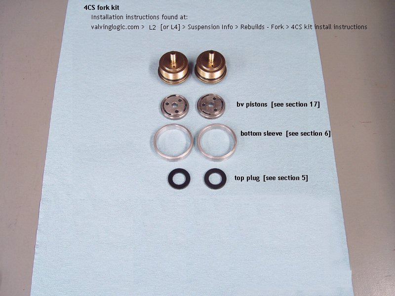
| 4CS kit pieces |
|
 |
Click on pictures to enlarge. |
|
|
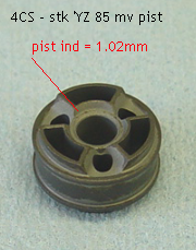
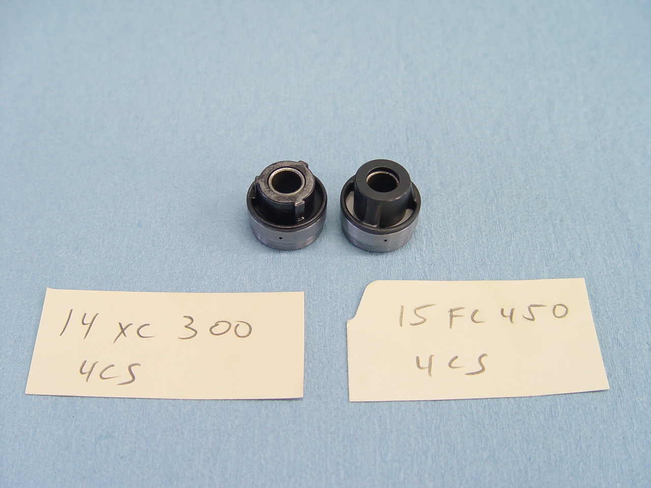
| 4CS kit - using stock mv piston |
|
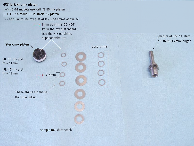 |
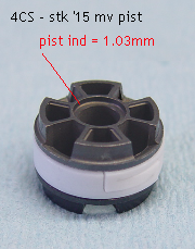
'15 and '16 models use the stock mv piston.
- stk '13-'14 mv pist ht = 11mm
- stk '15-'16 mv pist ht = 13mm |
|
|
| 4CS kit - using KYB YZ 85 mv piston |
|
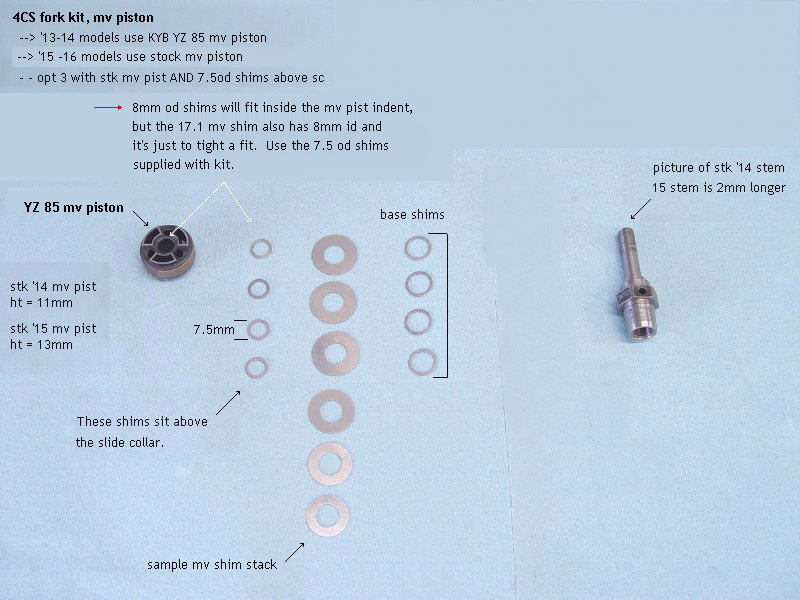 |
'13 and '14 models use the YZ 85 mv piston.
- stk '13-'14 mv pist ht = 11mm
- YZ 85 mv pist ht = 11mm |
|
|
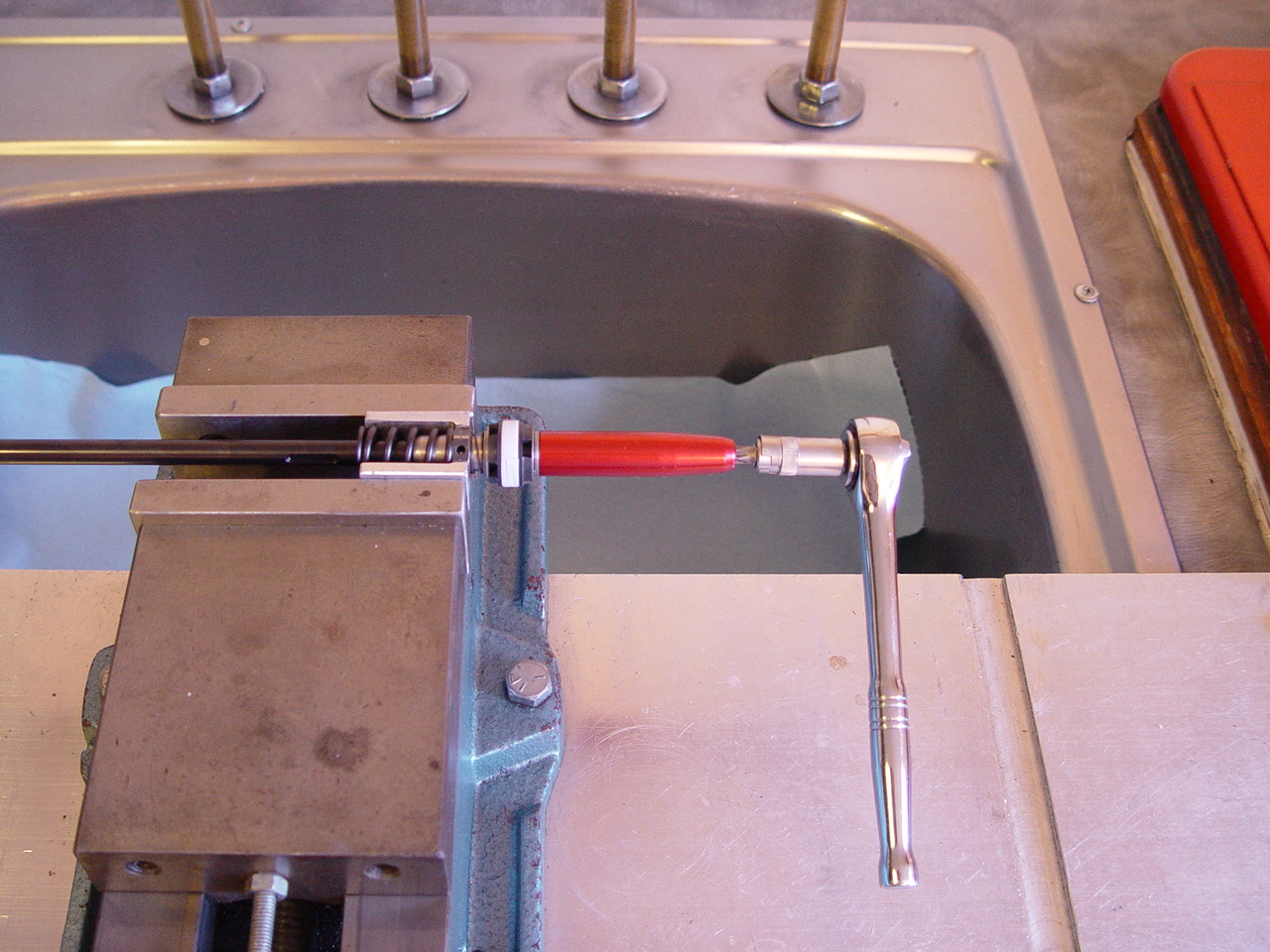
| 1) Lock 2 - 8 x .75 nuts together to loosen jamb nut. |
|
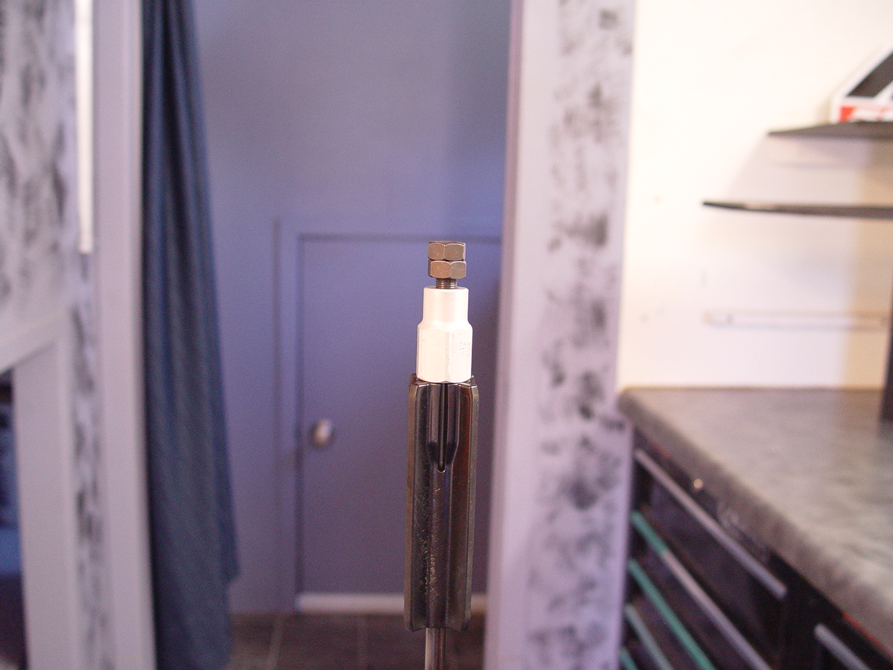 |
Click on pictures to enlarge. |
|
|
2) Remove base bolt. Pour out oil. Slide mv rod out the bottom.
|
|
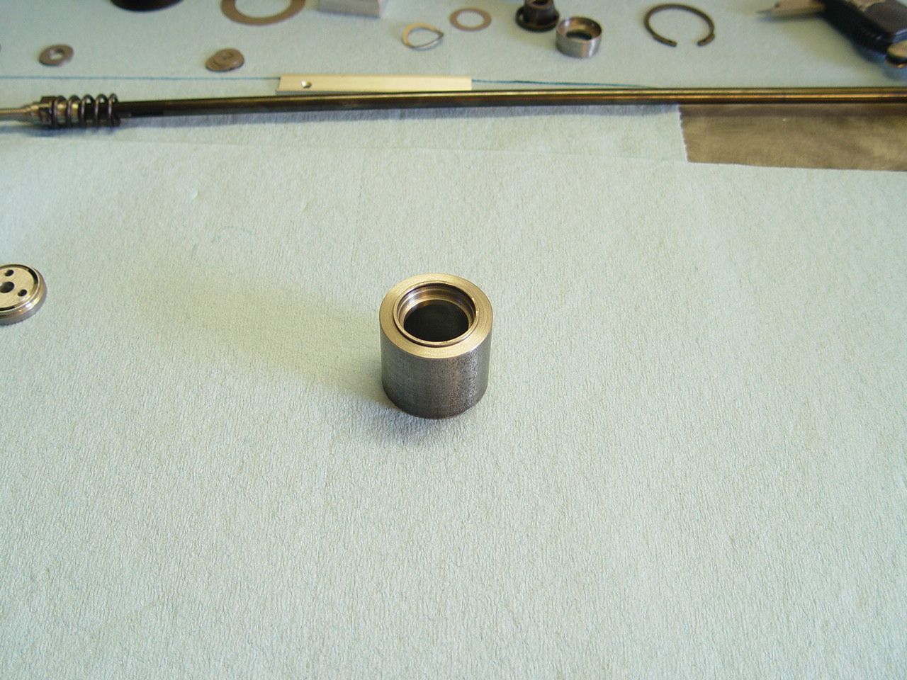
| 3) Remove cartridge tube. |
[top] |
 |
Push ctg tube out from bottom. |
 |
Remove plastic spring holder, metal washer and preload rings. |
|
|
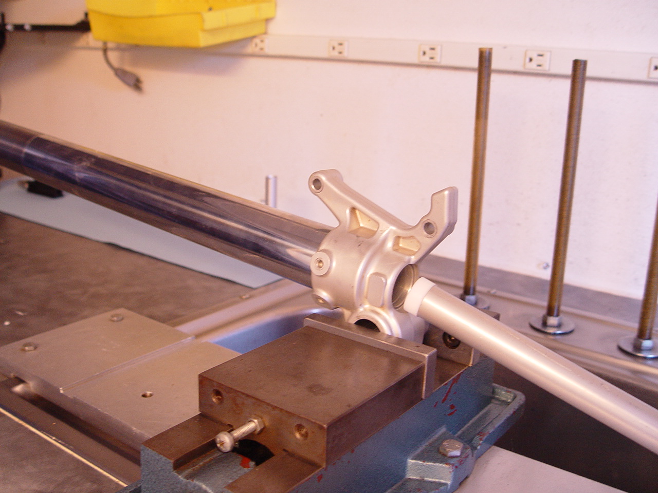
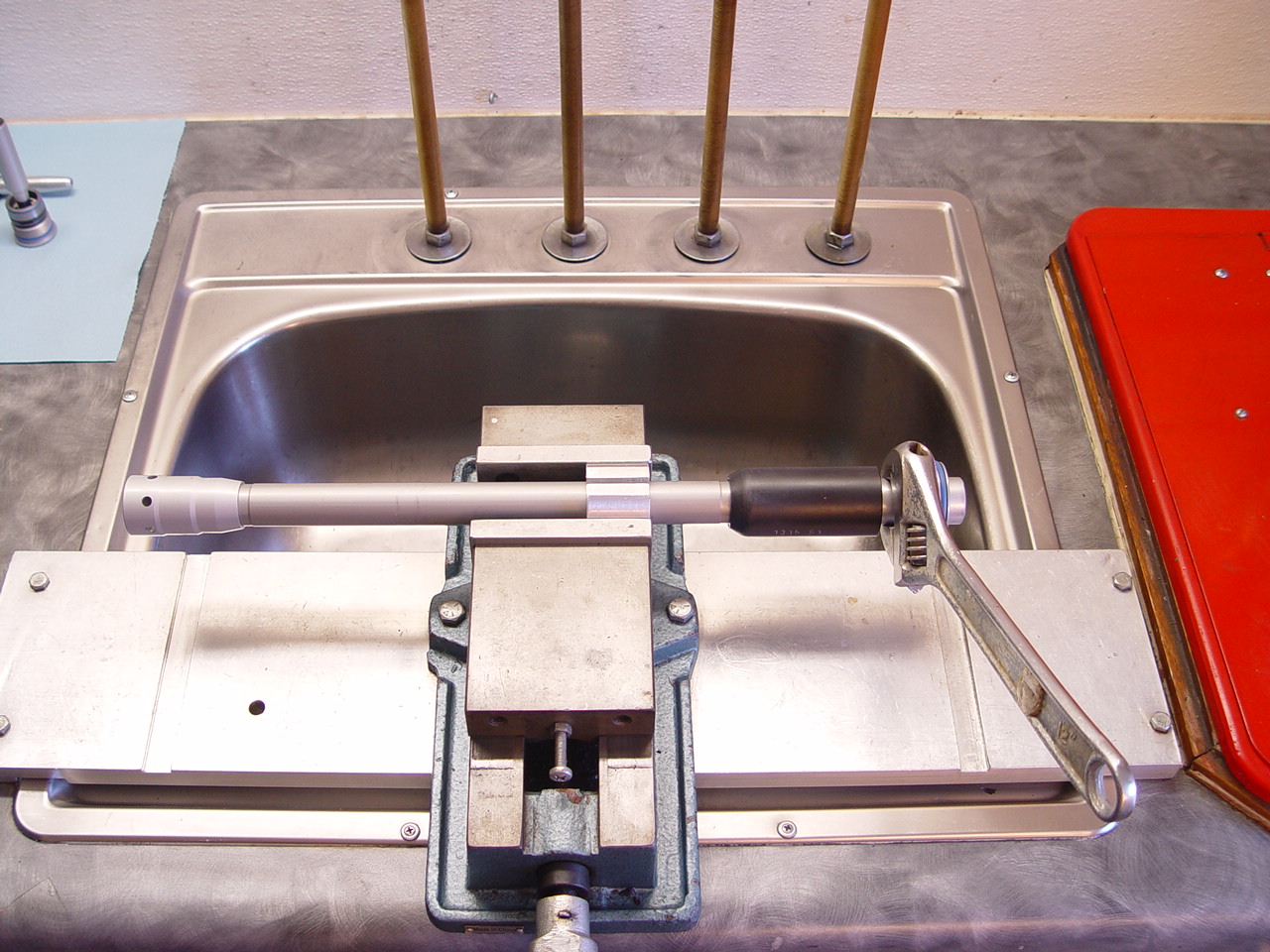
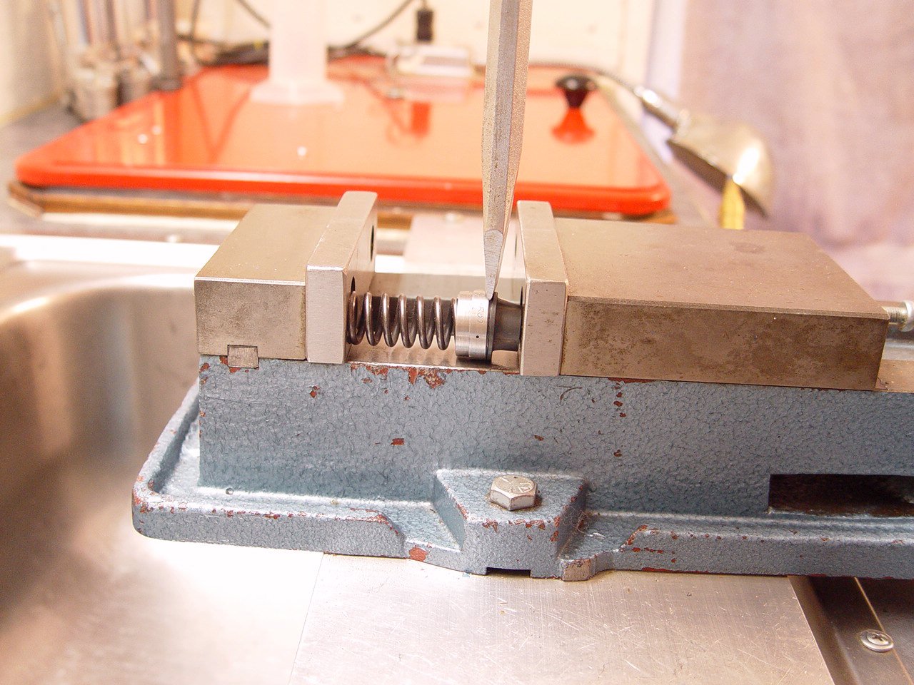
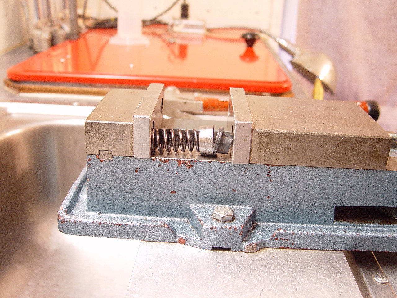
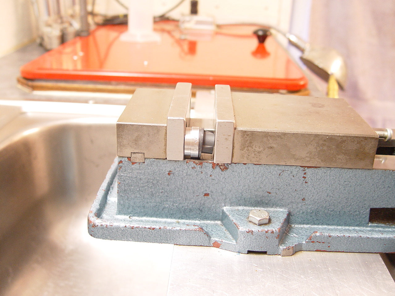
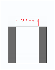
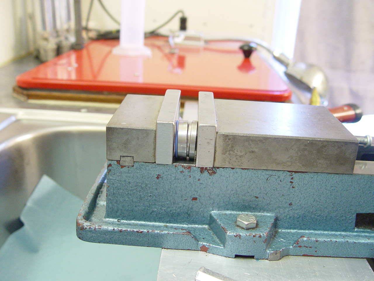
| 4) Clamp tube in vise with 24.6mm clamp block and disassemble. |
[top] |
 |
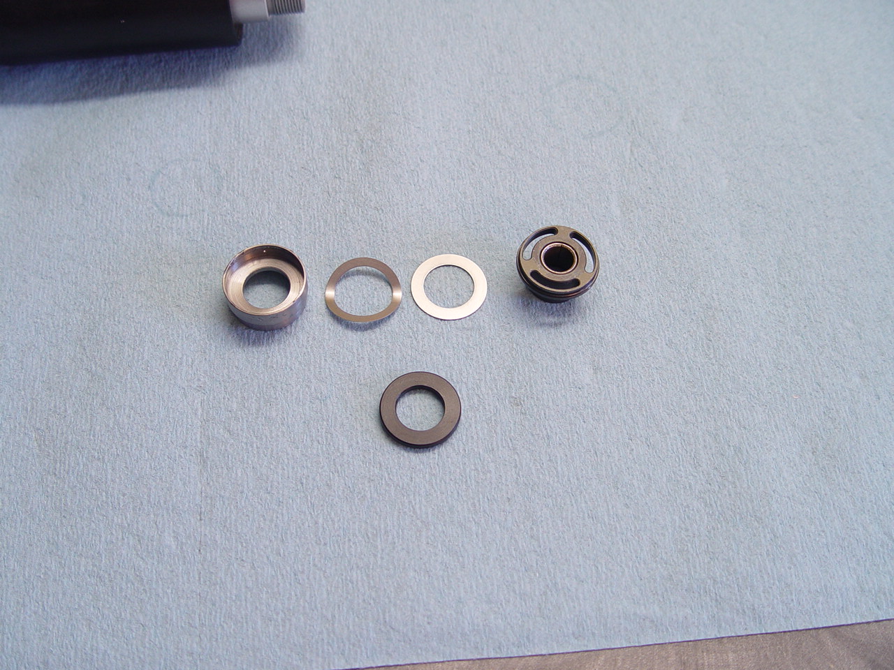
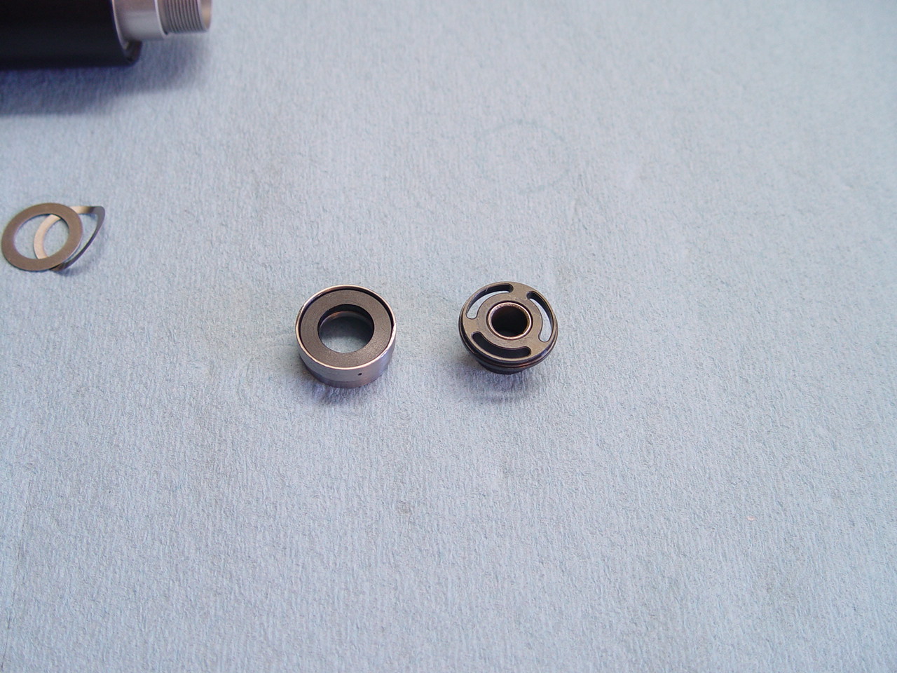
Remove the seal assembly. |
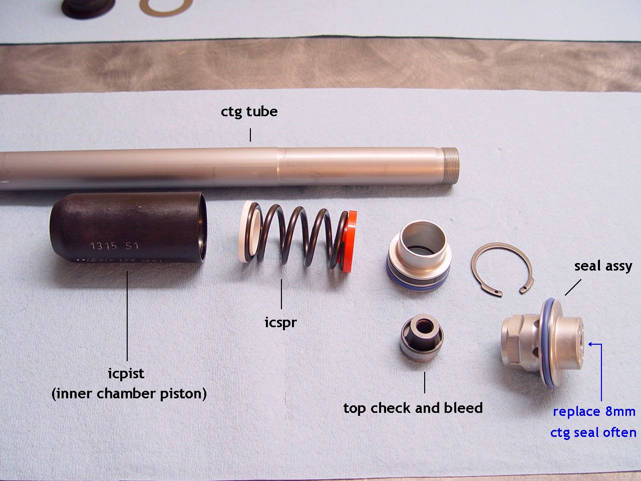 |
Remove seal assembly and slide off the icpiston (you do not have to disassemble the icpiston). Check for oil inside icpiston.
For some yet unknown reason, oil can accumulate in the icpiston. This fix is to simply clean the parts and reassemble. Not very scientific, but we haven't determined the cause.
We recommend replacing the 8mm ctg rod seal on a regular basis. No need if the forks are near new.
CAUTION!: Do not spray brake cleaners on the blue orings. It can remove the blue coatings on the oring surface. |
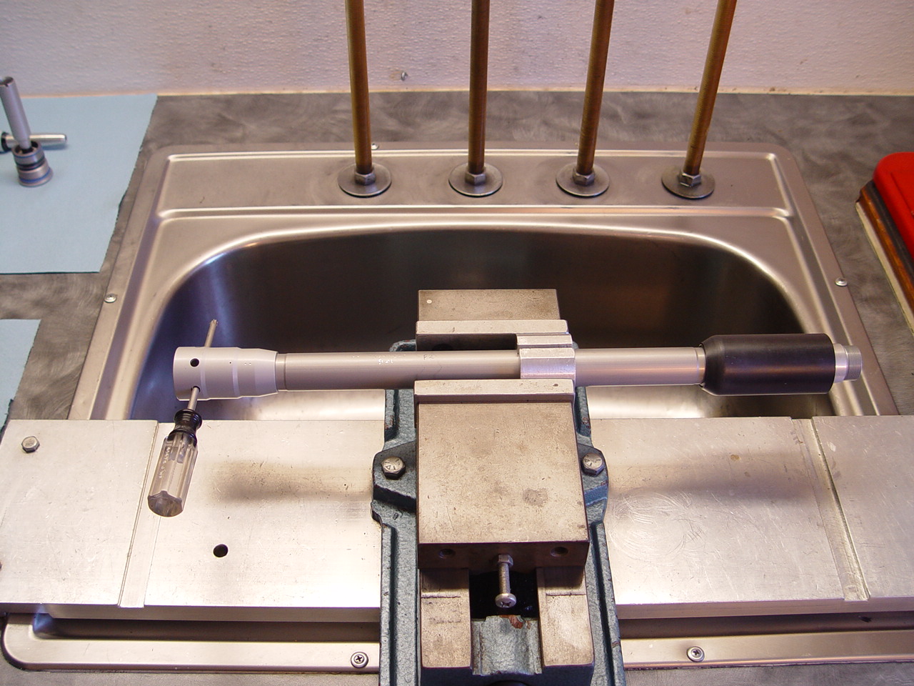 |
Check subtank (left end with screw driver), some earlier units have been known to be loose. The subtank does not need to be removed for the kit installation.
If it's tight, it's on there with some good loctite. Don't worry about breaking it loose with this quick check.
If it's loctited and needs to be removed, heat should be applied. |
|
|
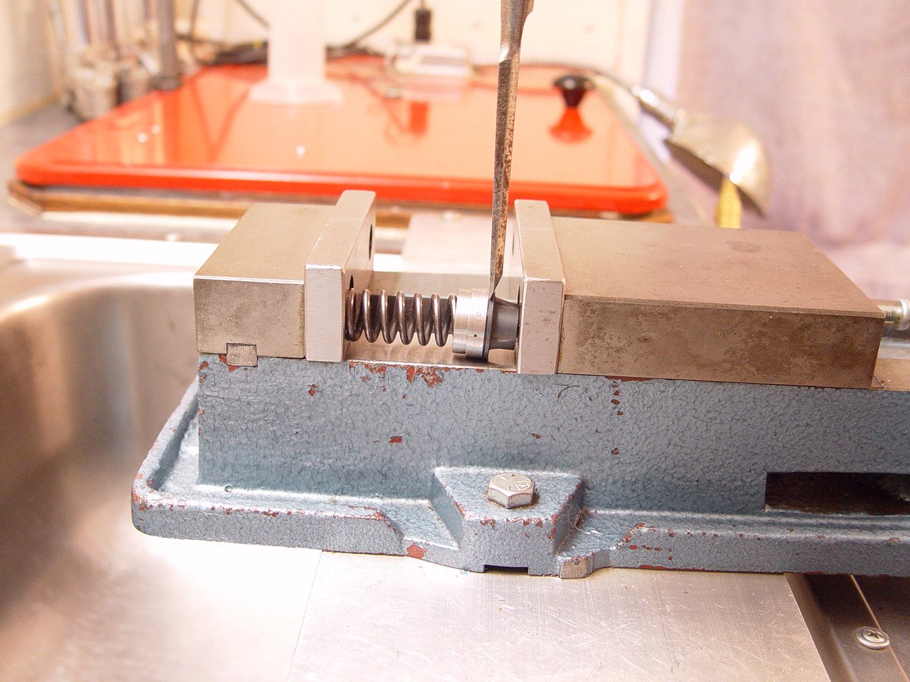
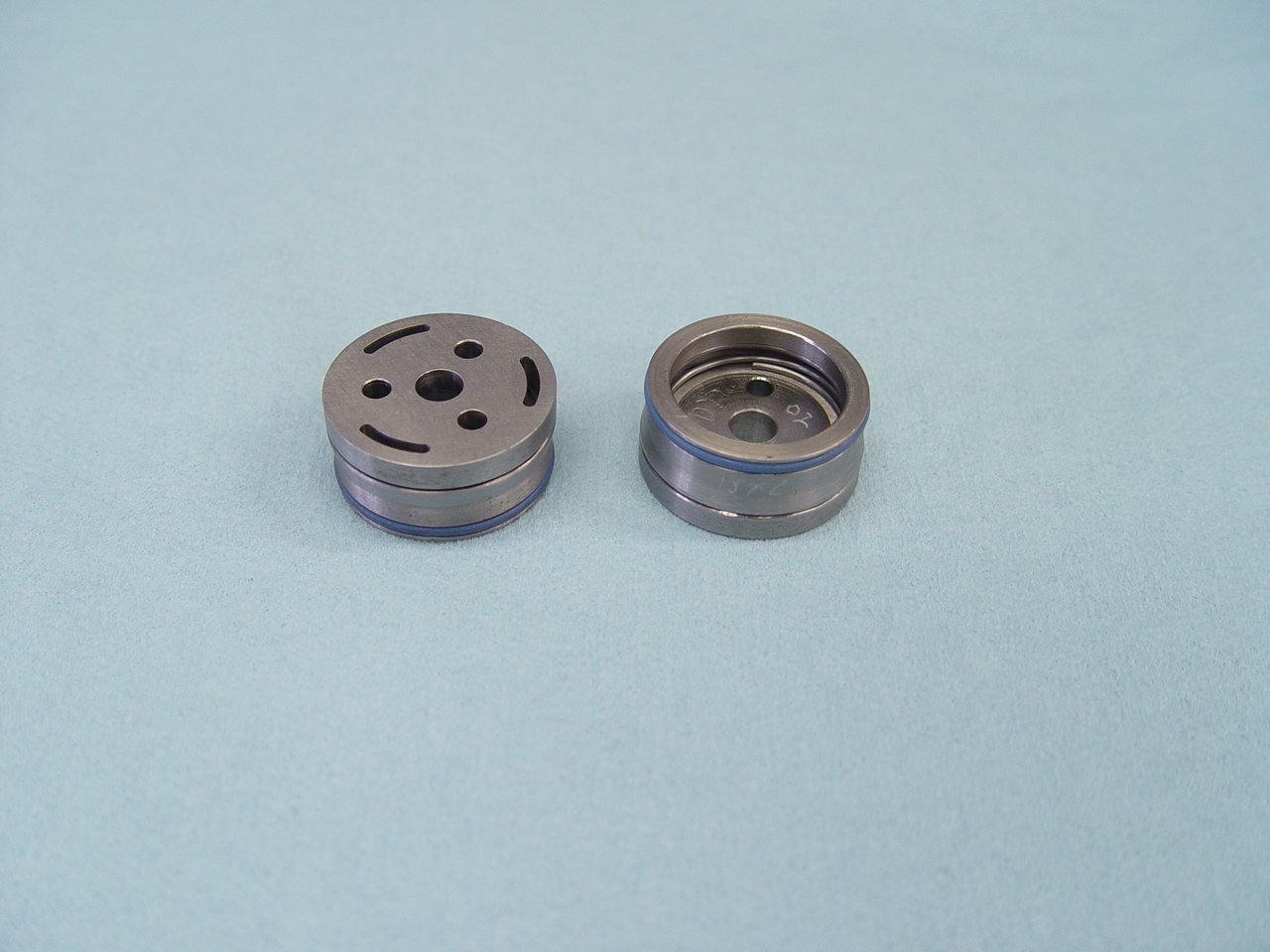
5) Split check assembly and install plastic plug.
---> The plastic plug closes the top check and bleed hole. |
[top] |
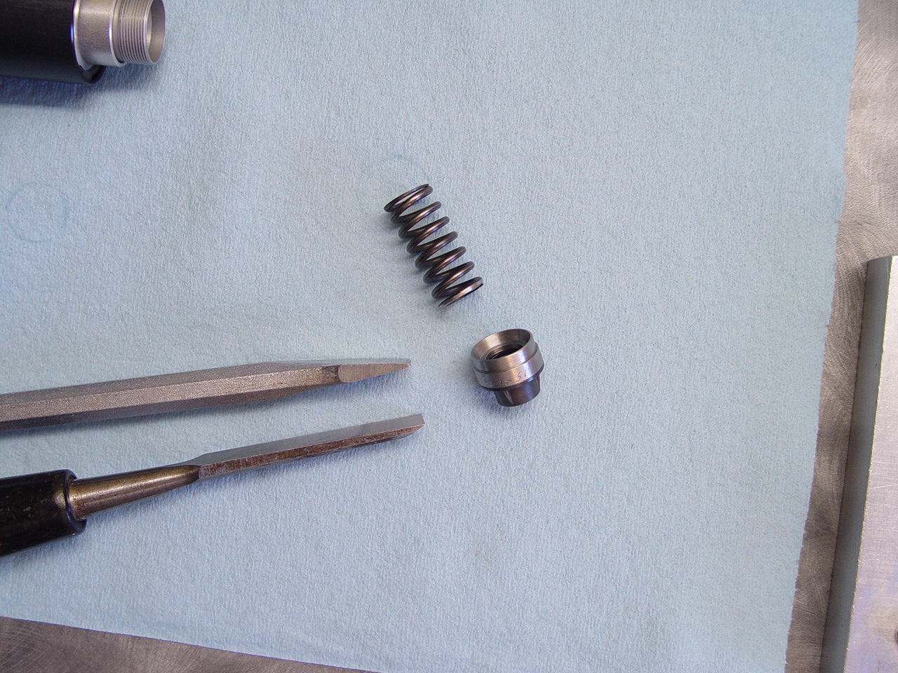 |
Start with sharp wood chisel and progress to cold chisel. |
 |
Start with sharp wood chisel. |
 |
Finish with fatter cold chisel. |
 |
|
 |
The plastic plug replaces the metal check shims and wave washer. |
 |
Press in the plastic plug (do not use check shim and wave washer). |
 |
Press together the pieces. |
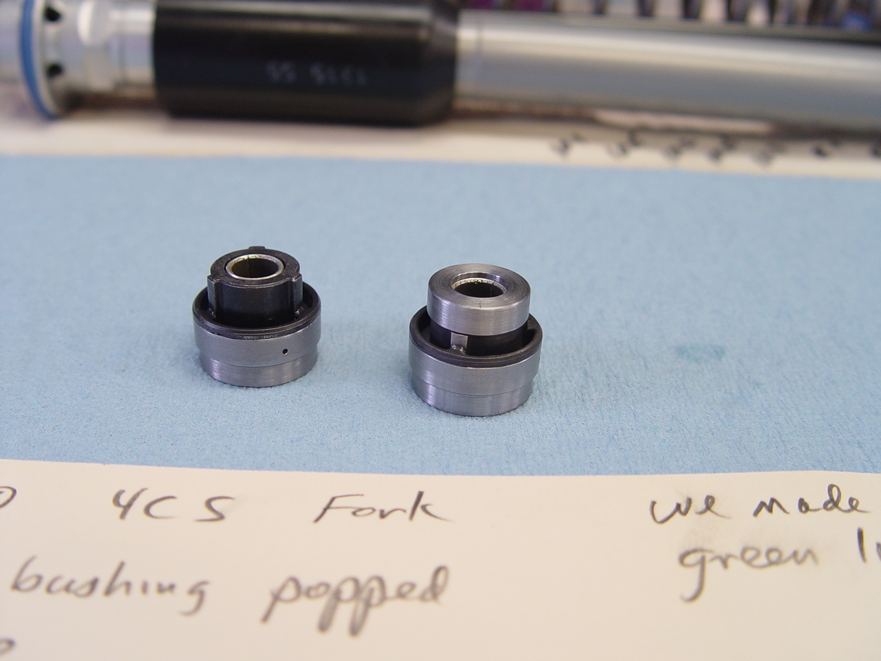 |
NOTICE!: The 8mm bushing can pop out of the older style check assembles found in some '14's.
Our fix was to machine and press on a metal cap. We also tried loctiting the bushing in place, but are unsure how strong the loctite holds.
|
 |
The factory corrected this in '15. |
|
|
6) Install bottom sleeve with loctite.
---> This closes the bottom bleed hole. |
[top] |
 |
A primer should be used when dealing with "inactive" metals such as anodized aluminum. We recommend Loctite 7649 primer. For maximum hold, we also use Loctite 680 retaining compound. But 680 is considered permanent, is expensive and hard to find, so red will do.
NOTE! The primer is a necessity! Also note that the primer can greatly reduce working time to as little as 3-5 seconds.
[click for additional info on primer] |
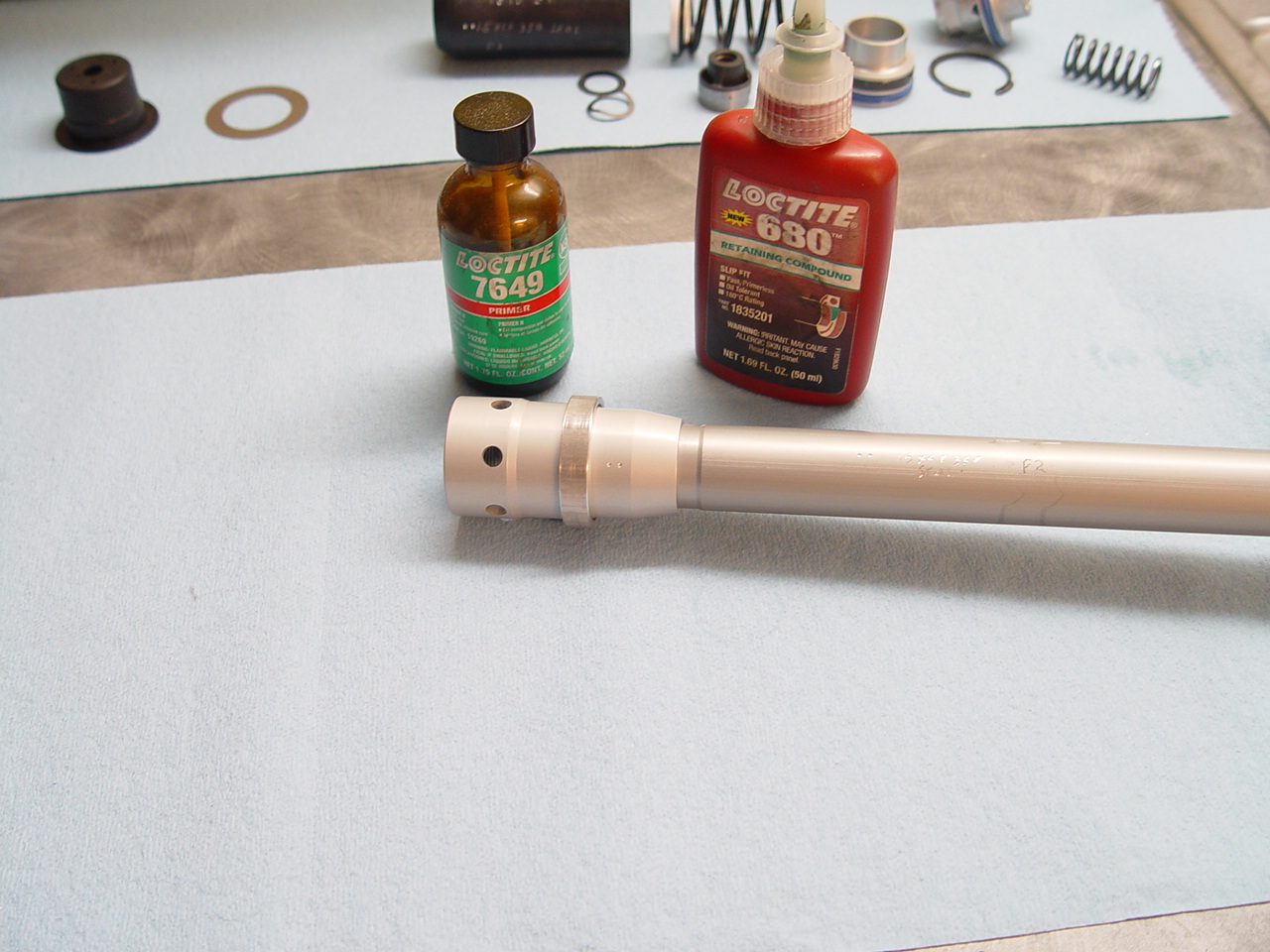 |
Apply loctite and position the aluminum sleeve over bleed hole.
The aluminum sleeve does not press fit, but is somewhat loose fitting. This makes for easier installation and gives a bit of space for the loctite. |
|
|
7) Reassemble icpiston and seal assembly. Use red loctite on seal assembly threads.
|
|
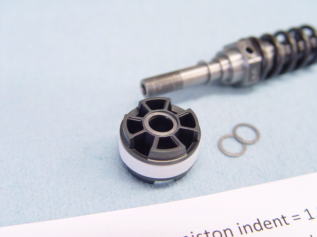
| 8) Remove mv piston and shims. |
[top] |
 |
|
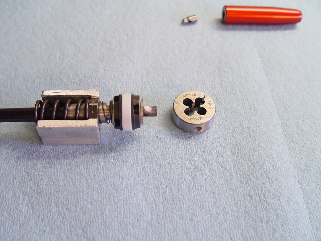 |
The factory thread seal makes it difficult to remove shims. We clean it with a 6 x .50 die. |
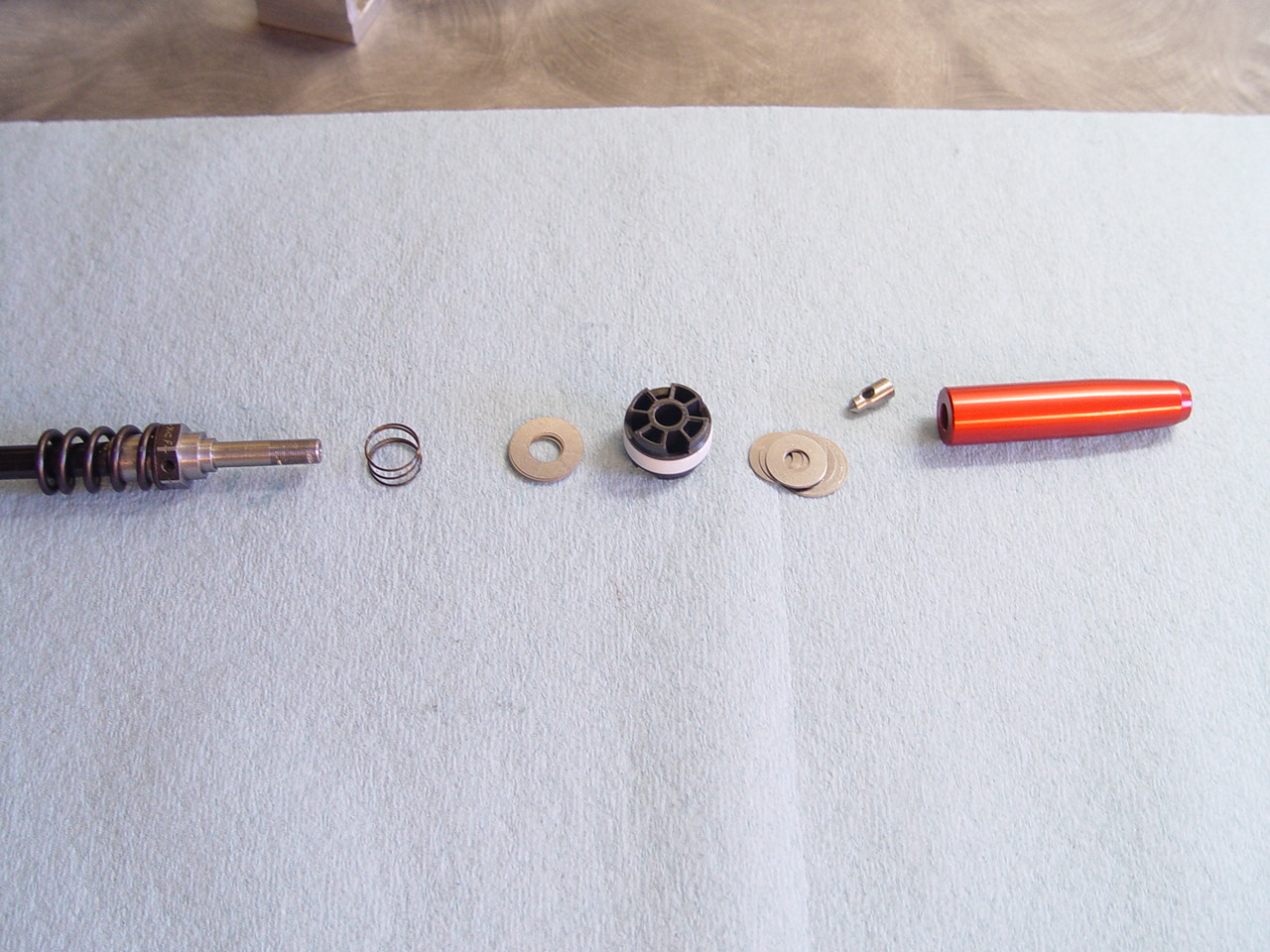 |
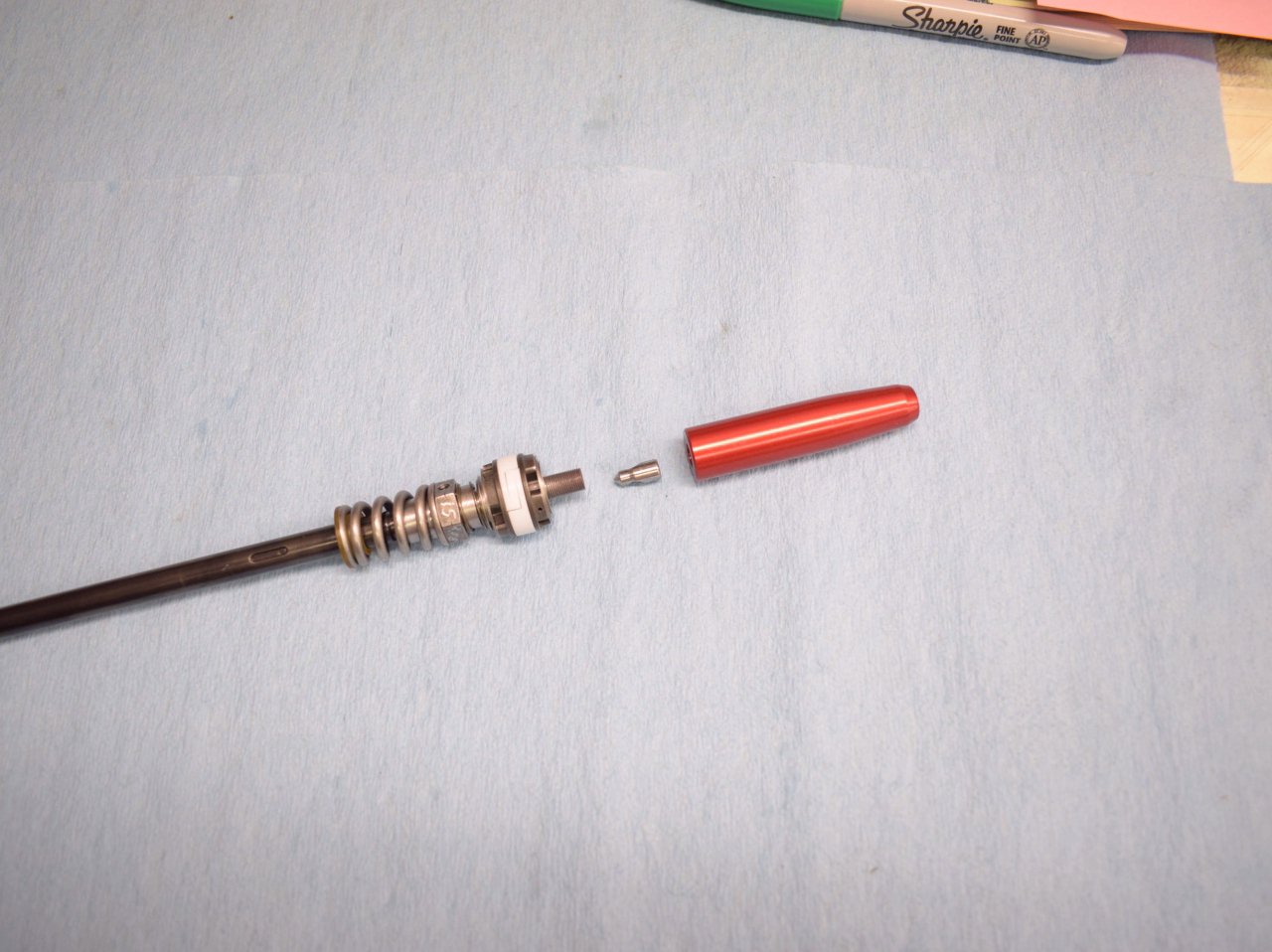
Stock parts.
The '14 and '15 have the long red and silver bullet, 16 has a stubby nut/bullet.
The 4CS kit uses these stock parts with different mv and reb stacks.
|
|
|
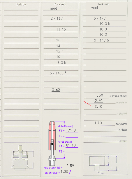
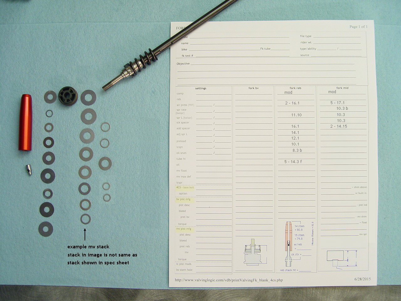
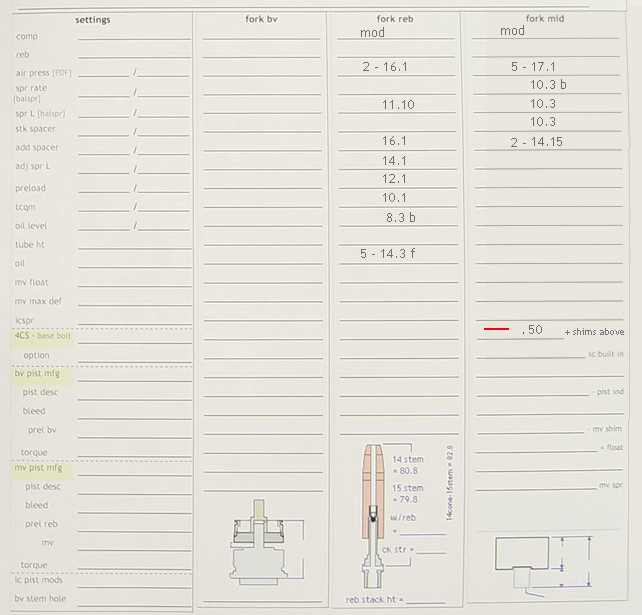
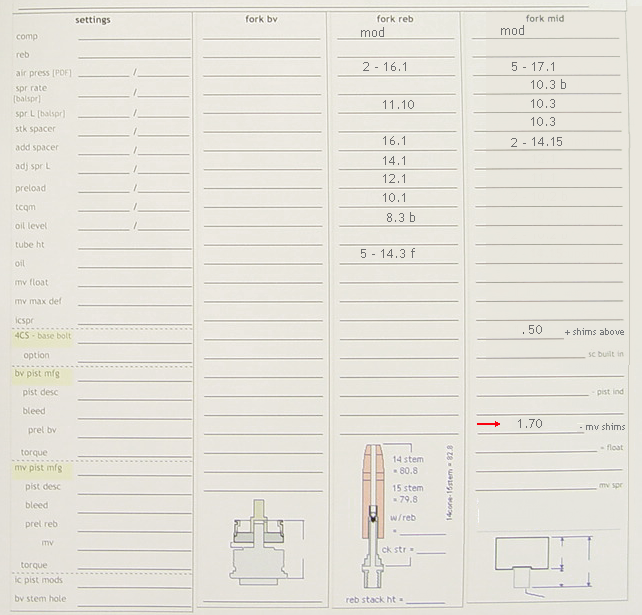
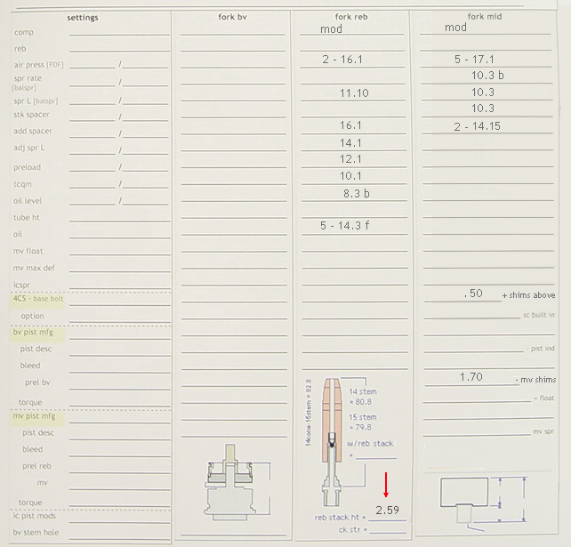
9) Mv spec sheet.
Print the 4CS spec sheet (adjust margins as needed or enable 'shrink to fit' before printing):
[print 4CS spec sheet]
---> This spec sheet makes it easier to record mv float. |
[top] |
 |
|
|
|
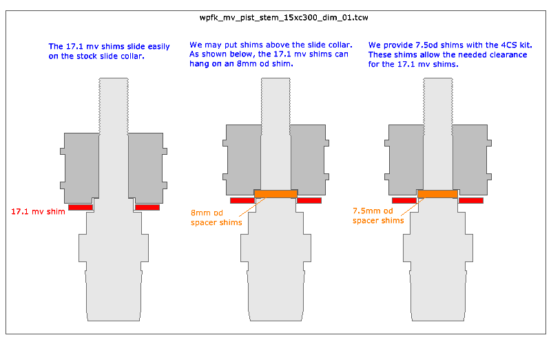
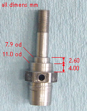
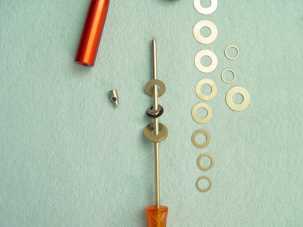
10) Measure thickness of 7.5mm od shims* that fit above the slide collar.
[* 7.5 od shims are supplied with kit. See section 13 for details]
---> This measurement is used to determine mv float. |
[top] |
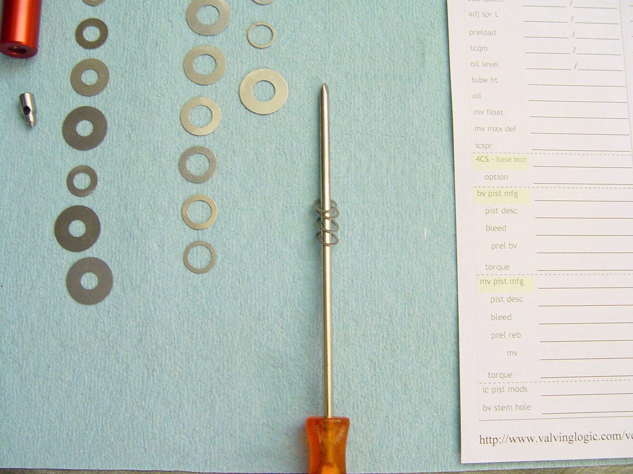 |
String the 7.5mm od shims above the sc, spray with contact cleaner and blow with air hose.
For accurate measurements, it is important to spray with contact cleaner and blow with air hose. |
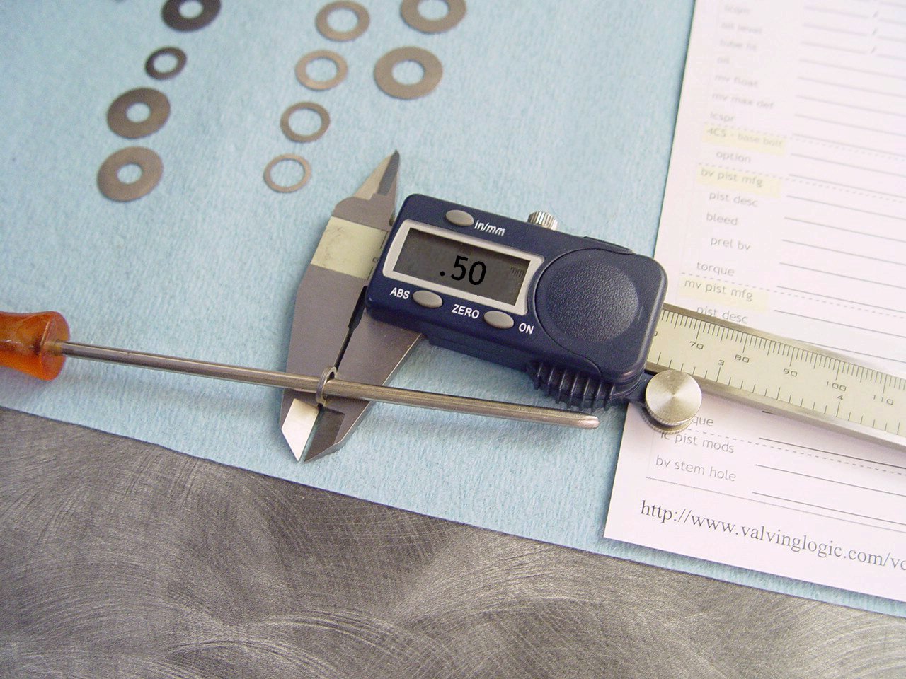 |
Measure thickness and record. |
 |
Note location of measurement. |
|
|
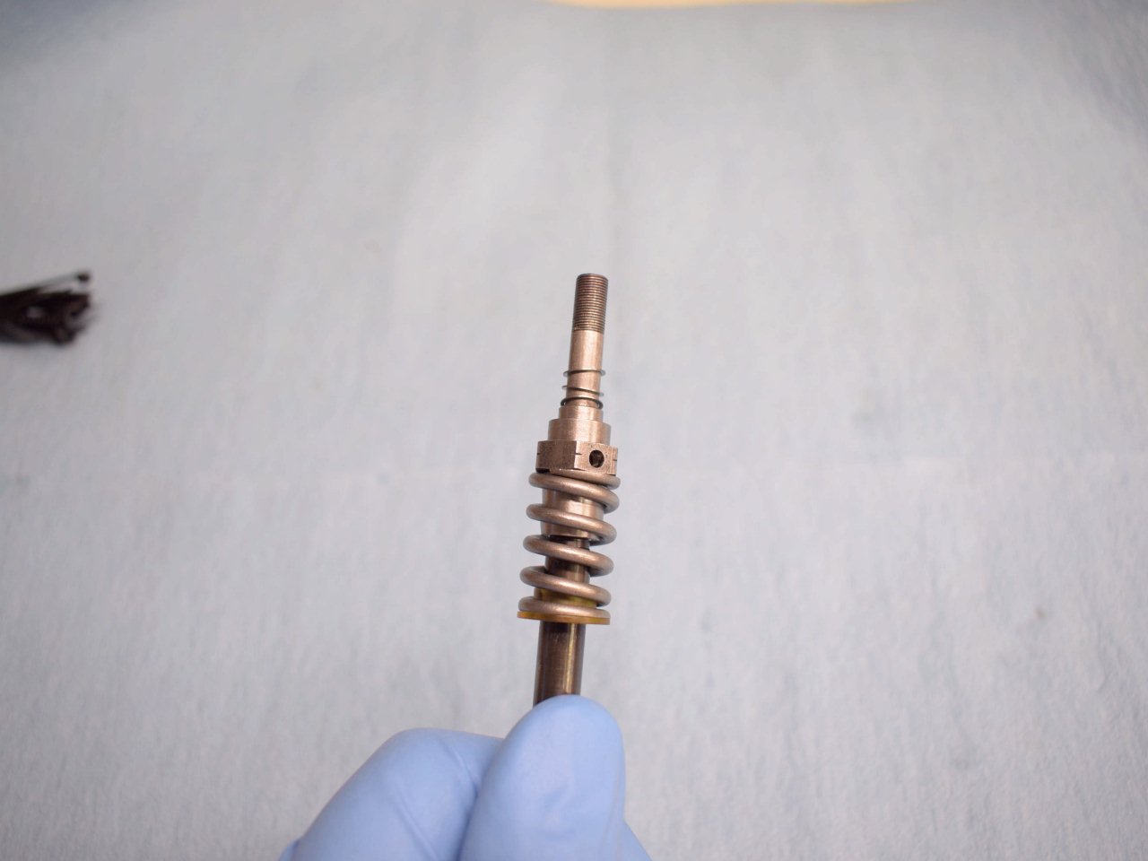
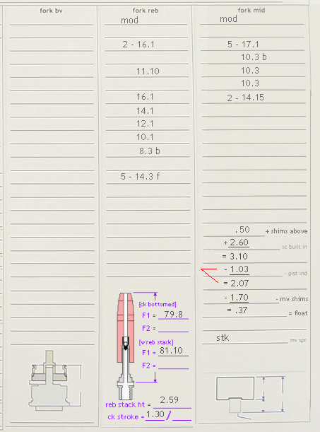
11) Measure and install the mv shims.
---> This is used to determine the mv float.
|
[top] |
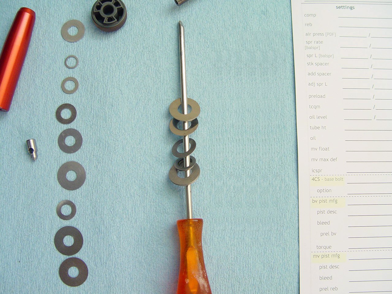 |
String the mv shims, spray with contact cleaner and blow with air hose. |
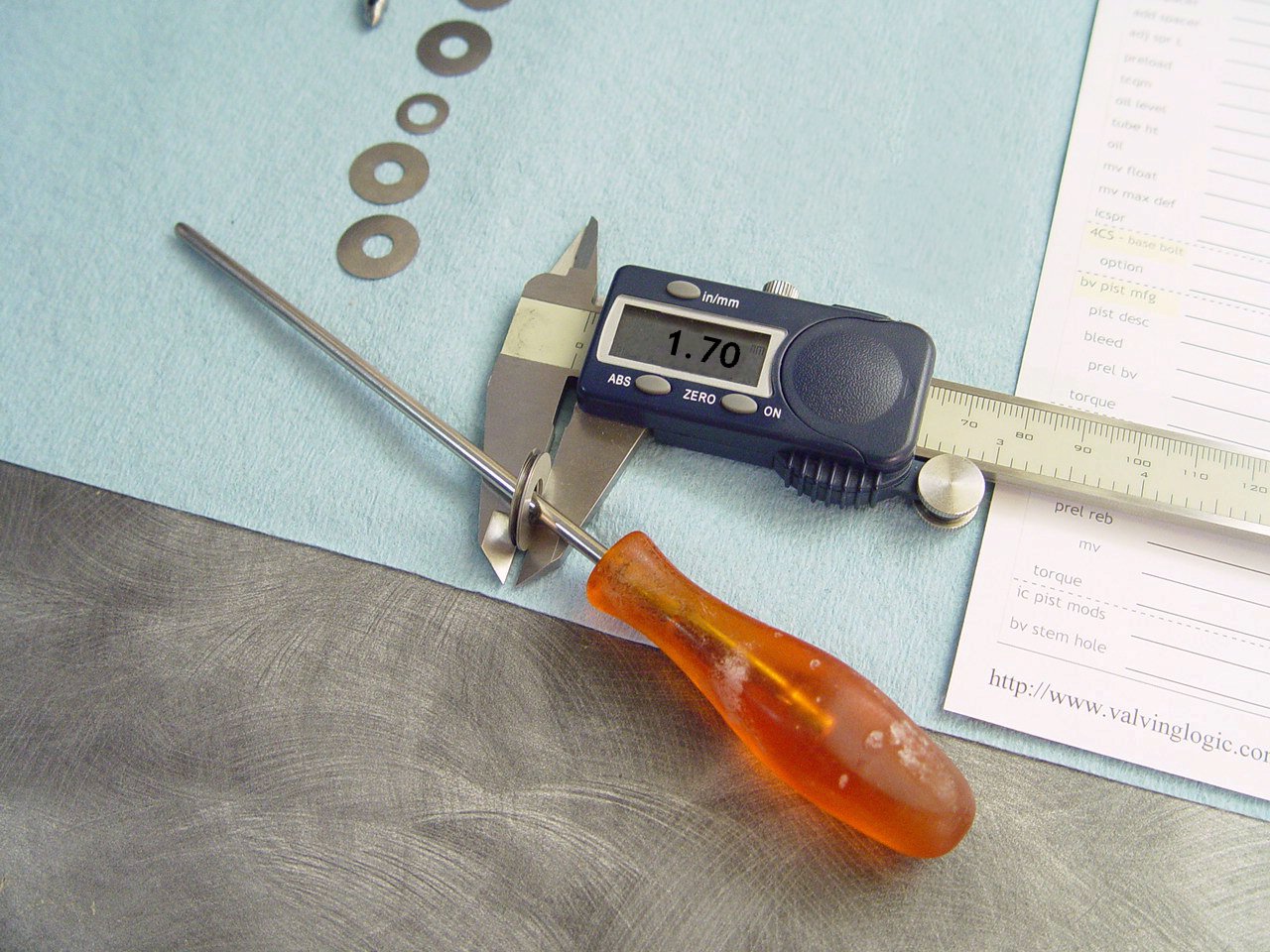 |
Measure thickness and record. |
 |
Note location. |
|
|
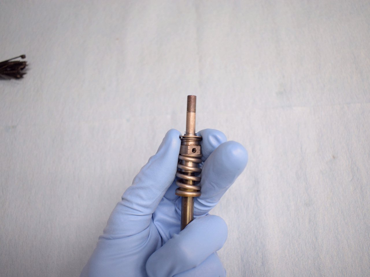
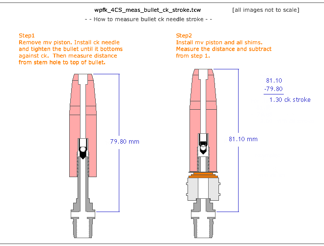
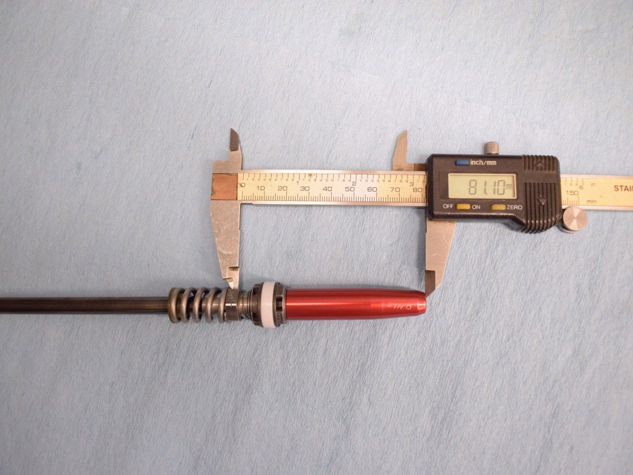
12) Measure and install the rebound shims.
---> This helps determine the bullet check needle stroke.
|
[top] |
 |
String the reb shims, spray with contact cleaner and blow with air hose. |
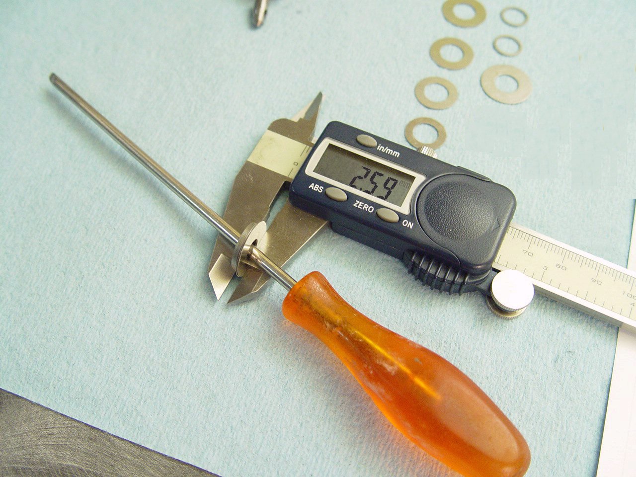 |
Measure thickness and record.
The reb stack thickness is not critical. This measurement is only used to determine bullet check needle stroke. |
 |
Note location. |
|
|
|
|
|
|
|
|
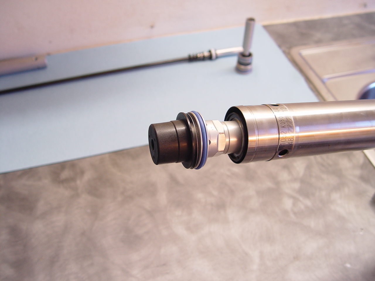
| 17) Remove stock bv piston and install mod piston. |
[top] |
 |
Unscrew hydrostop with wide blade and remove connecting nut.
|
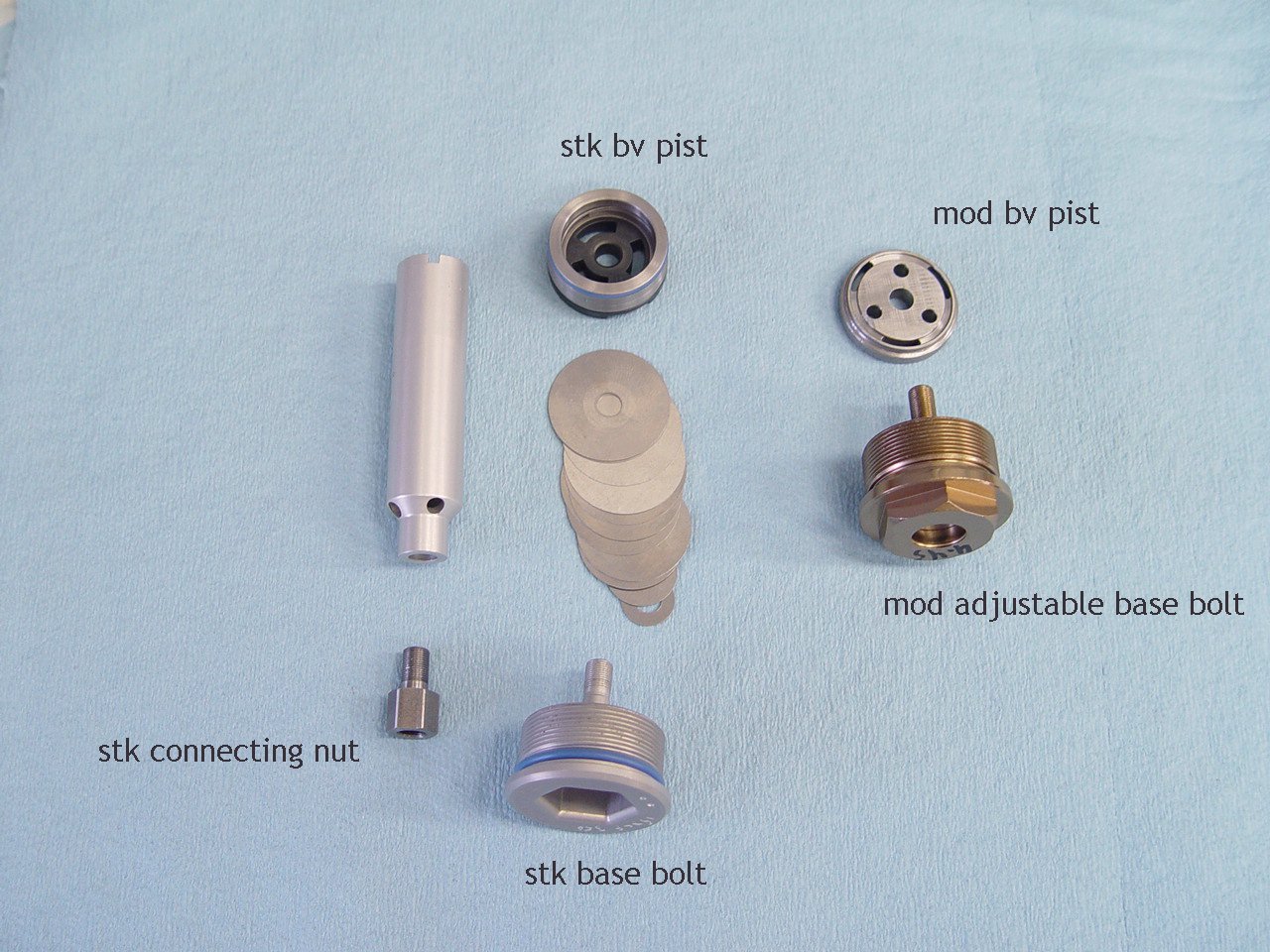 |
The stock bv piston and base bolt will be replaced. |
 |
IMPORTANT NOTE: Do not split the bv piston from housing if you choose to use the stock bv piston. See next image below.
Split the bv piston from the steel housing the same as the mv check assembly (#5). |
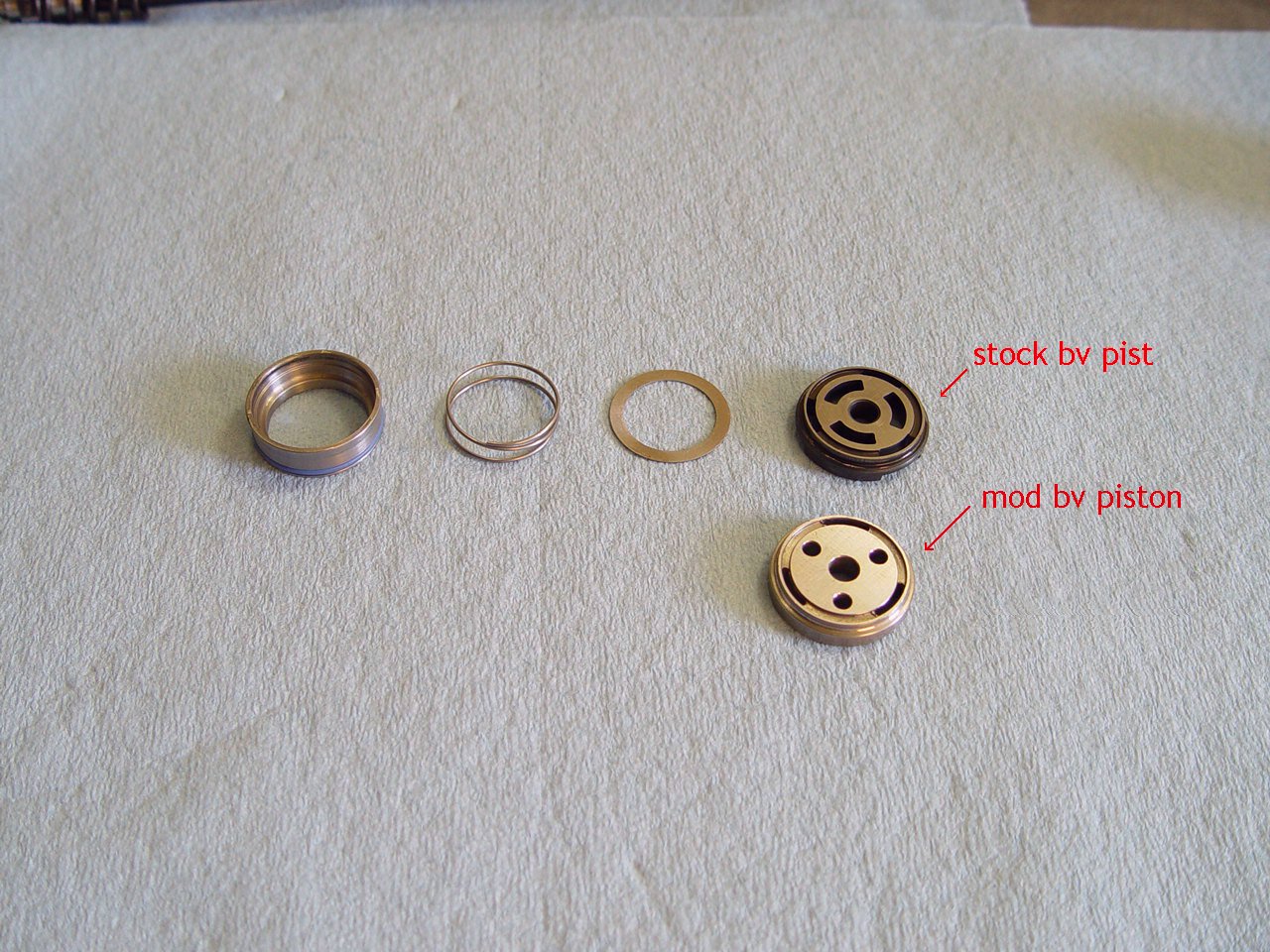 |
IMPORTANT NOTE: The mod bv piston is better suited for fast MX. Woods, Enduro, XC and trail use the stock bv piston.
Use the stock steel housing, check shim and spring. Replace stk bv piston with mod piston.
|
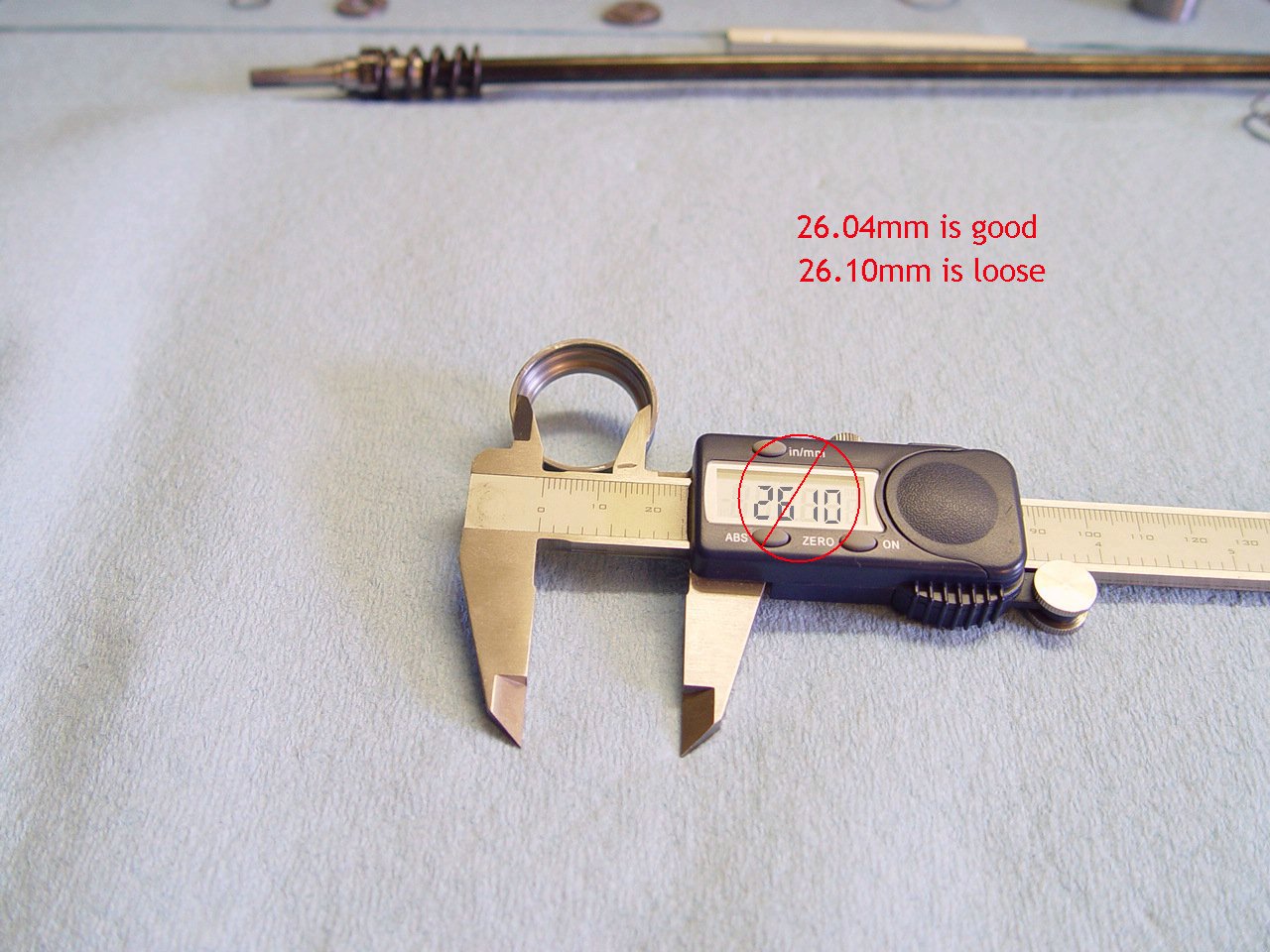 |
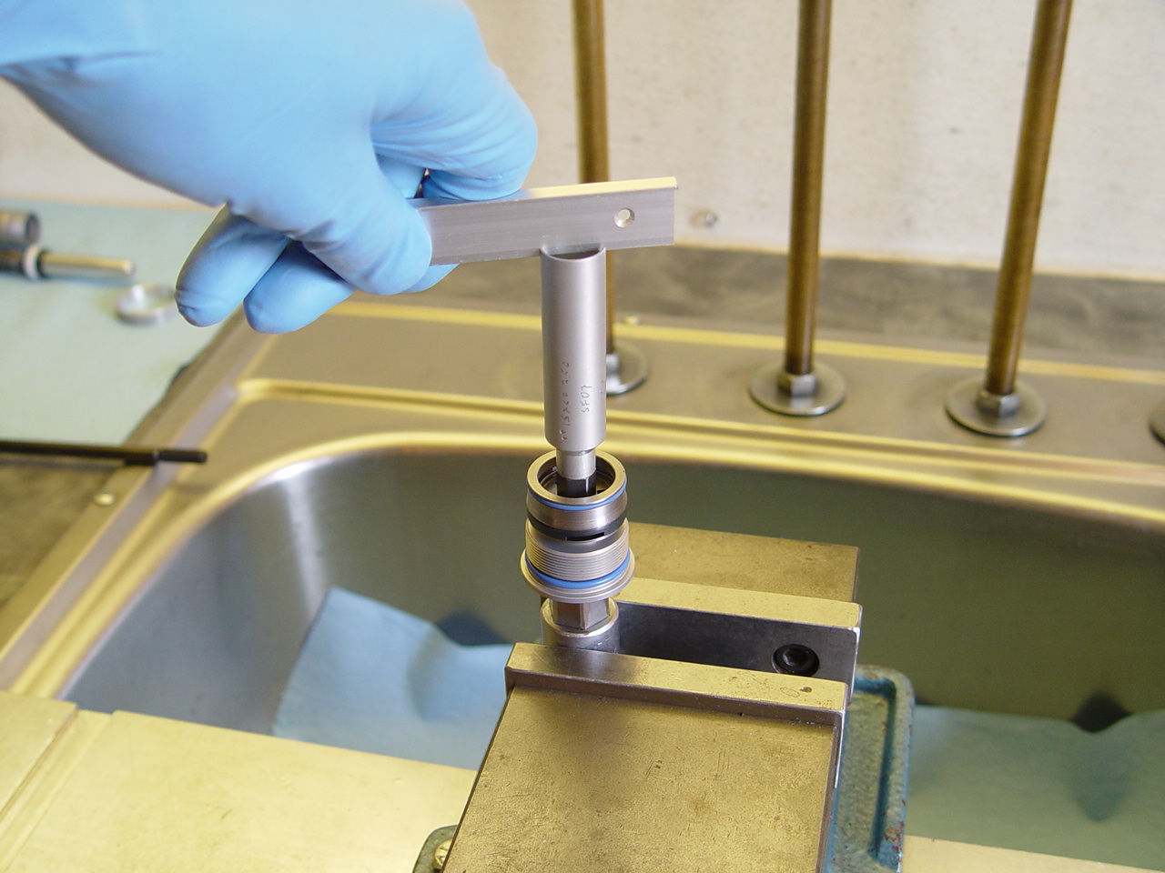
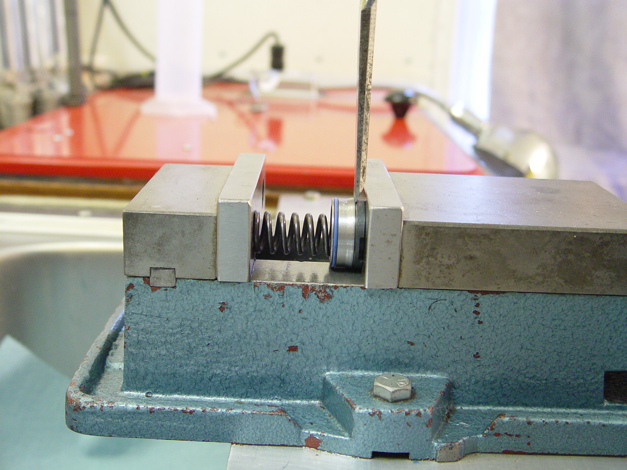
The mod bv piston may fit loose in some housings. We have noticed this in a couple 14's. |
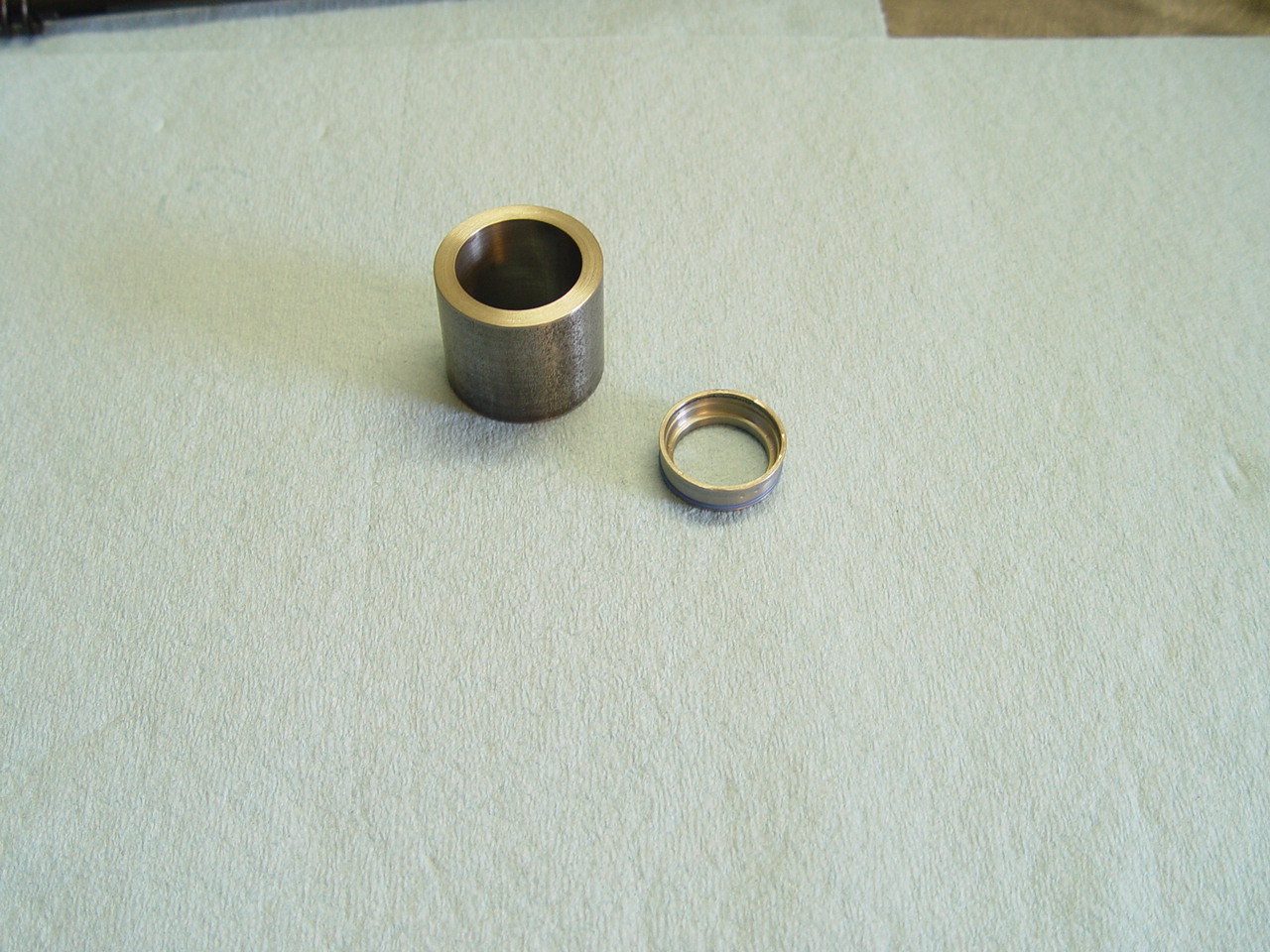 |
If loose, use tool to tighten top of housing.
 |
 |
Tap down on stock steel housing until it is flush with top of tool, then push out. This will tighten housing. |
 |
NOTE: Only necessary if you used the mod bv piston.
Press the pieces together. |
 |
Don't over do it. There may be a slight gap between the mod bv piston and housing. |
|
|
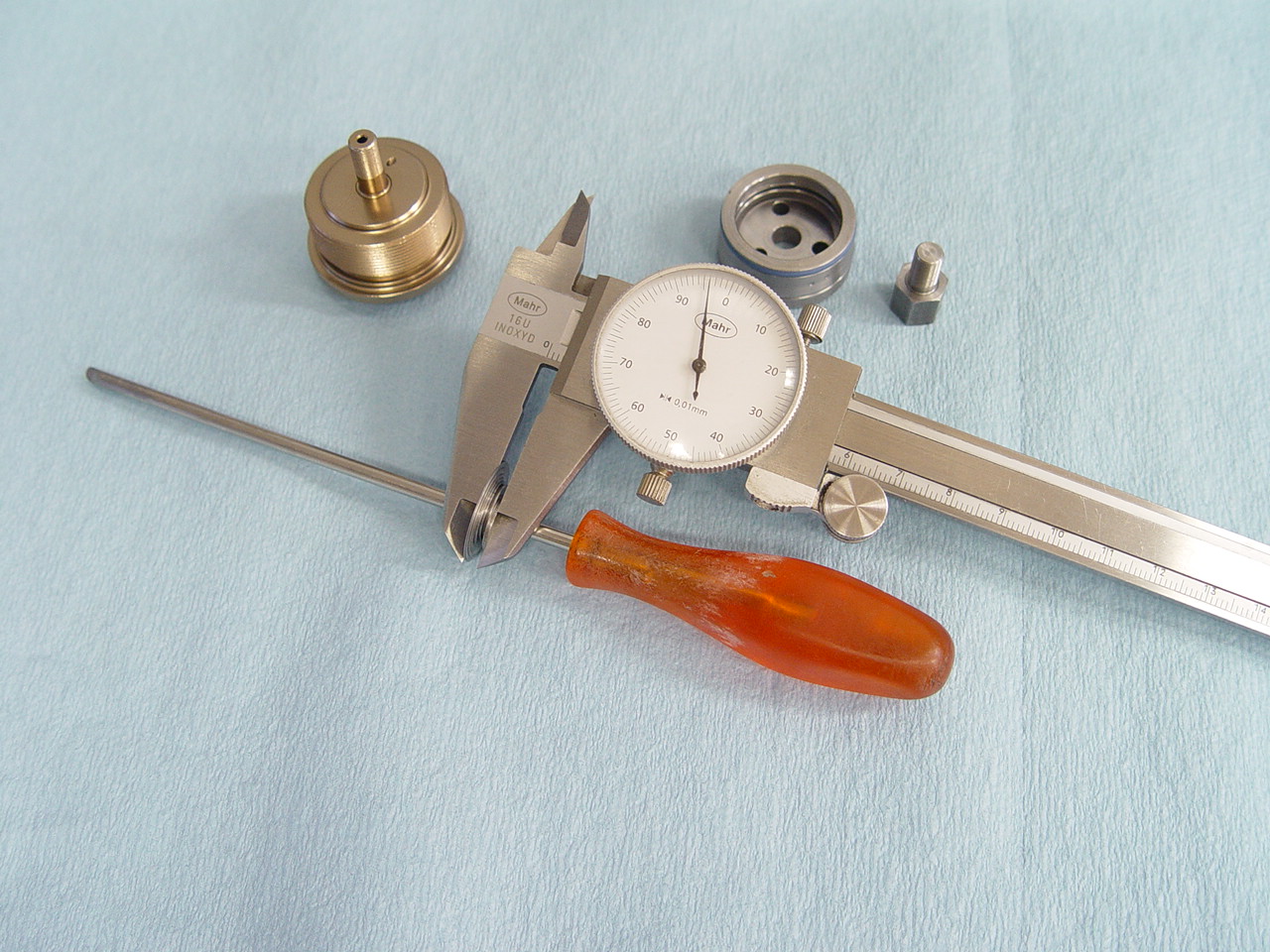
18) Drill stock connecting nut.
|
[top] |
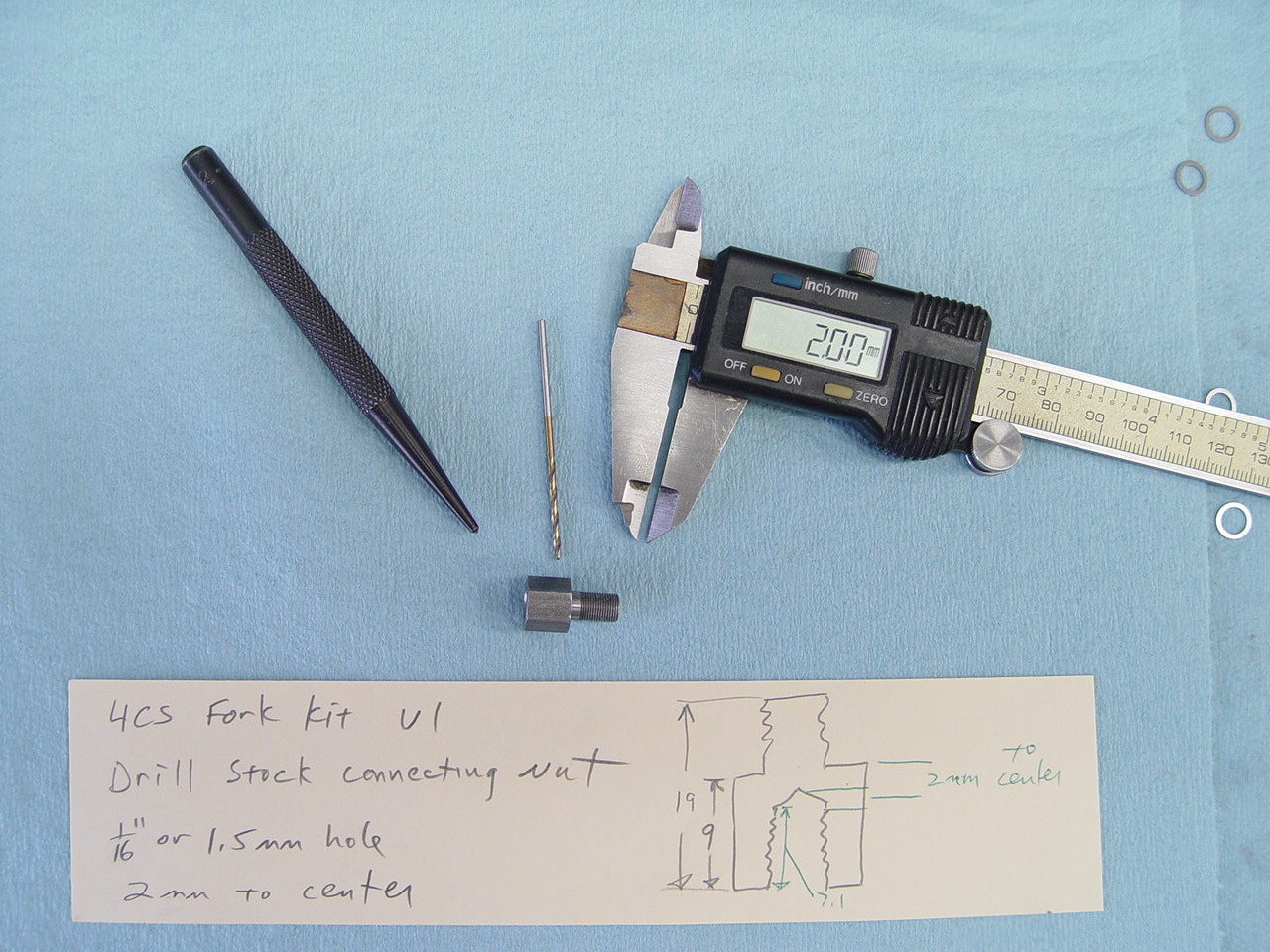 |
Drill 2 holes on opposite sides of the stock connecting nut. Use aprox 1/16 or 1.5mm bit.
This is required on the 14 and 15 models. The 16 has a regular nut and does not require drilling.
|
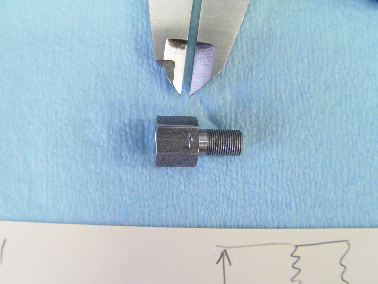 |
Use dial caliper and scribe a mark 2mm down. Use center punch to mark location for drill.
|
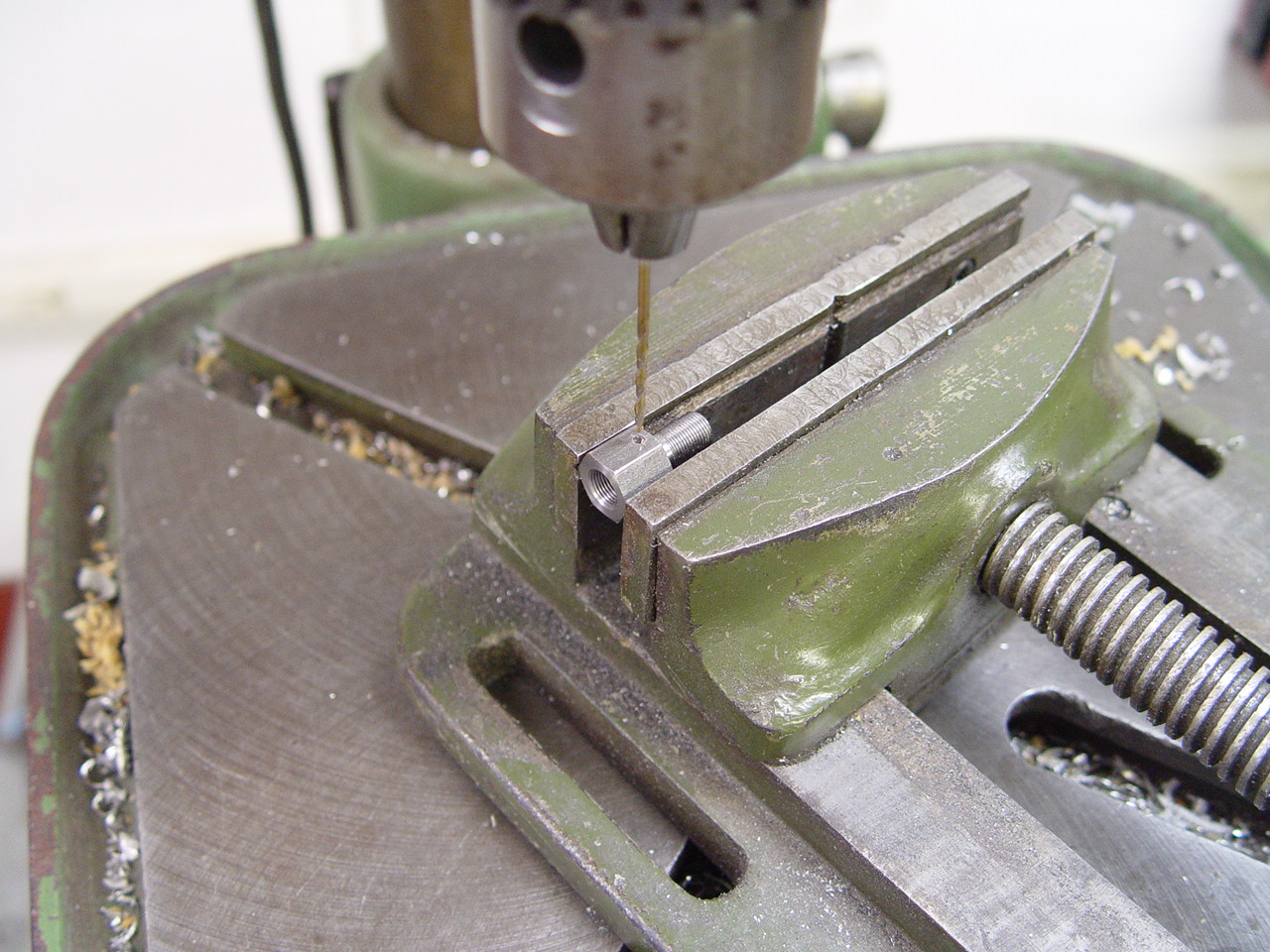 |
Secure the connecting nut in drill press vise. Drill slowly, especially when the hole is nearly through.
|
|
|
19) Assemble base valve.
---> These instructions are specific to the gp adjustable base bolt. |
[top] |
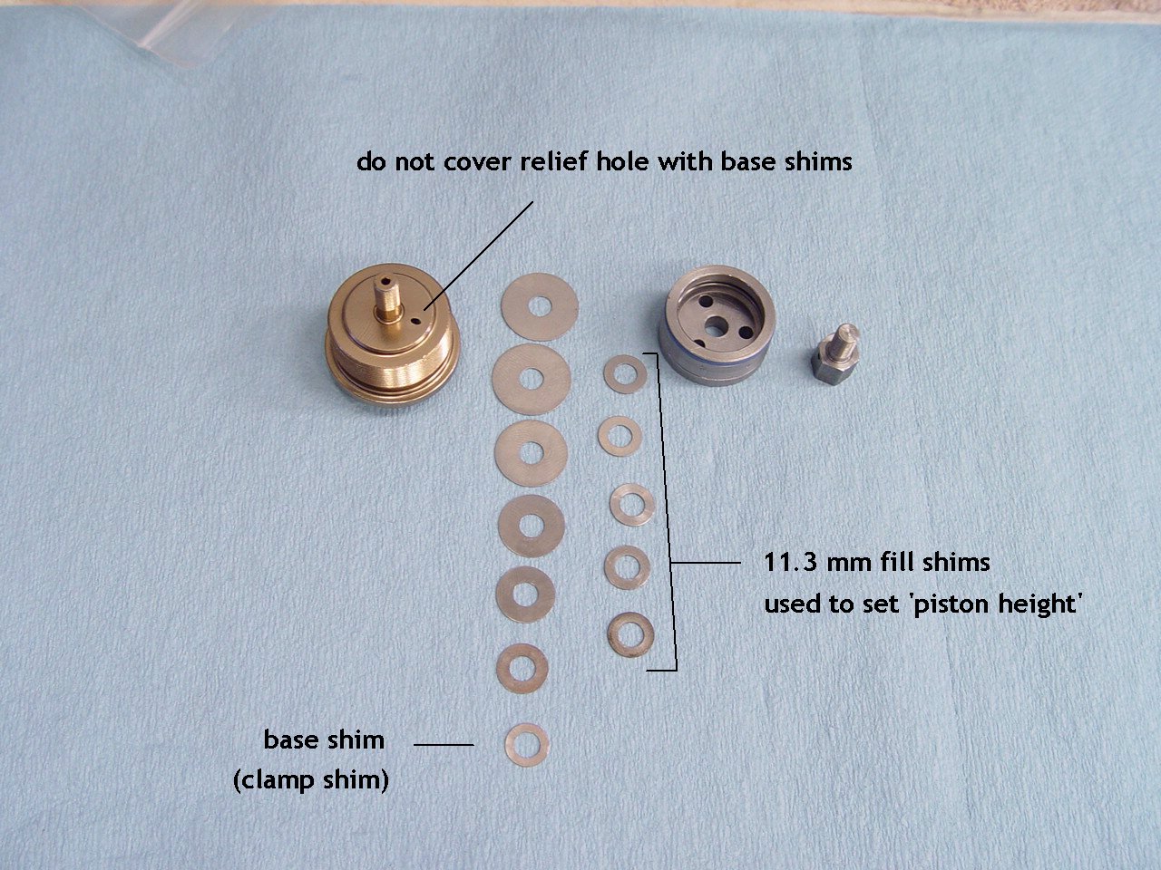 |
The adjustable base bolt has three options:
1) As shown to left, do not cover the relief hole. Use max 11mm base shim.
2) This image shows the base bolt that will accept a low speed shim stack and is used with the mod bv piston as shown on the left.

3) This image shows the low speed circuit has been machined and is used with the stock bv piston.  |
 |
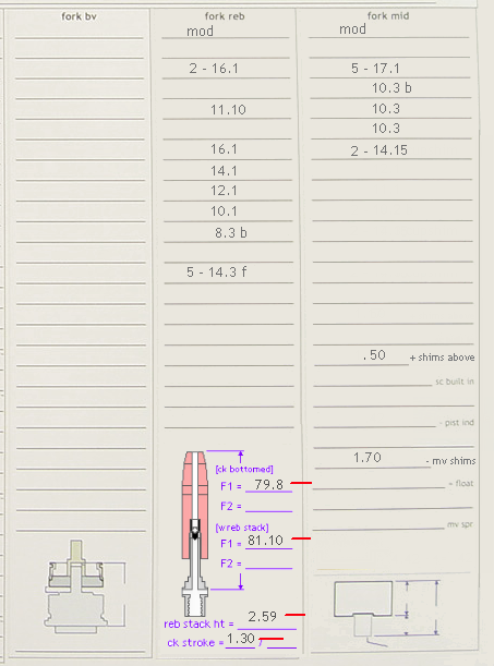
Measure the thickness of the bv stack. The stack thickness must fit within a specific range. We use:
--> bv stack thickness range = 2.3 to 3.8 mm
--> we generally set the stack height around 2.35 - 2.55 mm
|
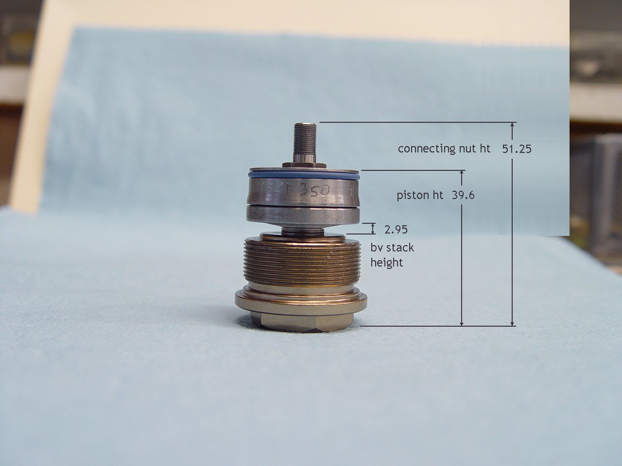 |
IMPORTANT NOTE: These dimensions will vary depending on the exact build. Exact dimensions are provided with each spec sheet.
The assembled bv piston height must fit within a specific range. In this example:
- - bv stack thickness = 2.95 mm
- - piston ht = 39.6 mm
- - connecting nut ht = 51.25
Use loctite and torque the nut 35 in/lbs.
|
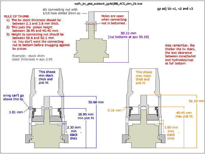 |
IMPORTANT NOTE: These dimensions will vary depending on the exact build. Exact dimensions are provided with each spec sheet.
This diagram shows the minimum and maximum range for the bv stack thickness and piston heights.
|
|
|
- 05-18-18
- These installation instructions show the basic modifications needed to install the 4CS fork kit.
- We now have new and improved specs and will provide additional details with each spec sheet.
|
|
|
| |