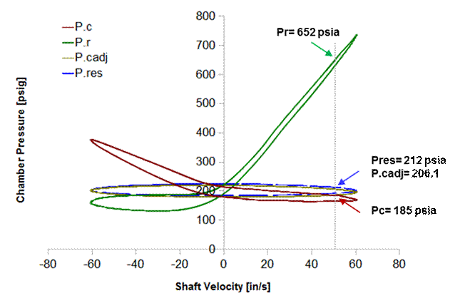
A walk through the seal drag calculations for the Canadian valve data. First, here is a plot of the chamber pressure data for the 60 in/sec run. The calculations below are for the data at 50 in/sec, this is the signal data from the Rhoerig software not the gauge data. The pressure measured in each chamber are marked on the plot.
First we compute the force on the shaft from the reservoir gas pressure and the force added by the pressure drop across the compression adjuster.
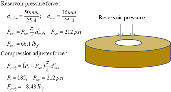
For this 50 in/sec data point on the rebound stroke the pressure drop across the compression adjuster is negative since the shock is trying to suck fluid out of the reservoir. With P.c less than P.res the compression adjuster force is negative for this point.
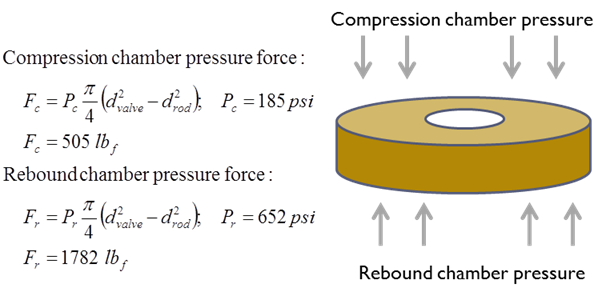
Next we worked out the forces on the mid-valve:
And finally the force balance on the shaft:
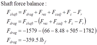
The forces acting on the valve surfaces are less than the measured shaft force. For the force balance the difference is assumed to be seal drag. So at 50 in/sec in the rebound stroke the seal drag force for the Canadian valve test was -359 lbf. Adding all of the other data points I get a seal drag plot like this plotted against the pressure drop across the valve:
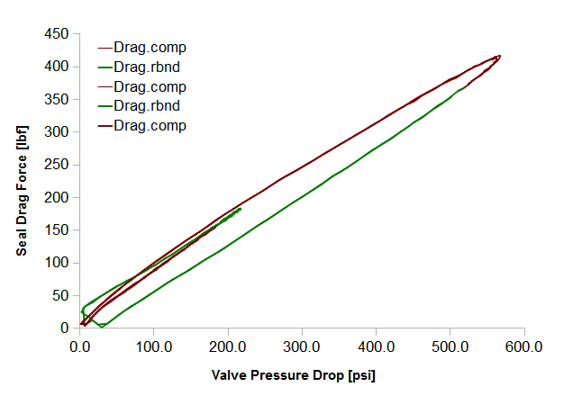
The seal drag force on the compression and rebound stroke both increase as the pressure drop across the valve increases.
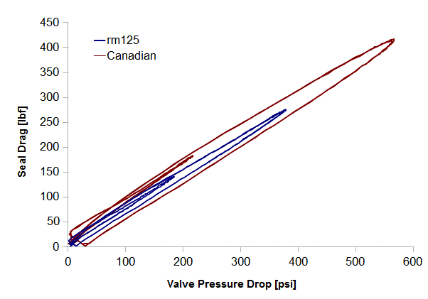
Comparing the seal drag for the Canadian valve to the rm125 test you sent earlier shows that both valves have about the same drag. The Canadian valve might be a little higher.
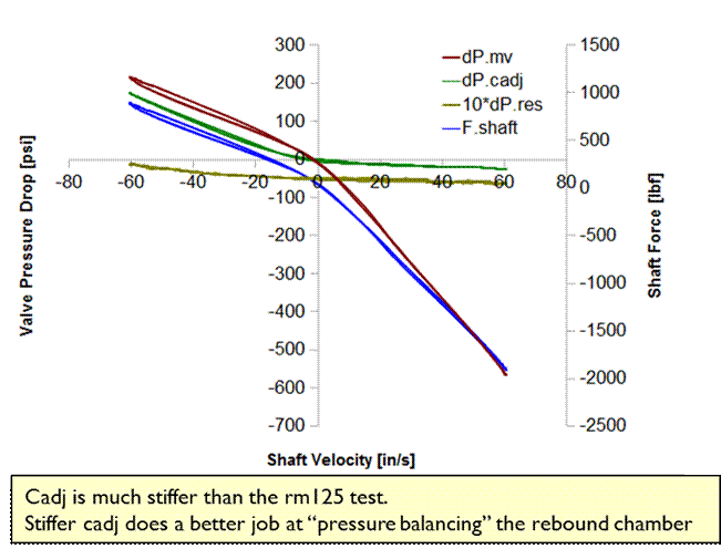
Here is a plot of the pressure drop across each valve. The interesting thing here is the compression adjuster is supplying much more backpressure than the rm125 test. With the higher backpressure the Canadian valve is closer to “pressure balanced” on the rebound stroke.
Here is the above data replotted to show the damping force contribution from each valve. Since the compression adjuster pressure only acts on the 16mm shaft there is not much damping force provided by the compression adjuster. If you look close you can see the compression adjuster shaft force.
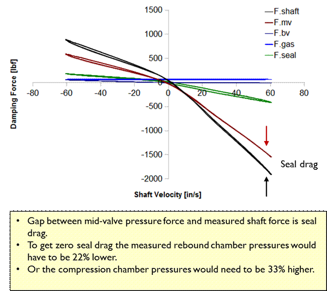
The “gap” between the damping force produced by the mid-valve and the measured shaft force is assumed to be seal drag. If the pressures measured in the rebound chamber were 22% lower the seal drag would work out to be zero. Likewise if the compression chamber pressures were 33% higher the drag force would be zero.