Understanding the separator or transition shim is the key to manipulating two-stage valve stacks.
Separator shims
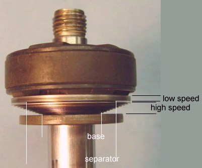
Picture 1 shows a typical two stage stack found in current model dirt bike shocks.
Picture 1
The stack consists of:
low speed stack
separator (transition) shim
high speed stack
base (clamp) shim
We refer to this as a two stage-taper stack.
The separator shim determines how and when the low speed stack makes contact with the high speed stack. We call this the point of contact (poc), which is the distance the top stack deflects before hitting the bottom stack. In the simplest of terms, if the separator shim thickness was .2mm (.008") then the top stack would deflect .2mm (.008") before hitting the bottom stack. But this would only apply if the separator and base shim diameters are the same. The actual point of contact is not always equal to the separator shim thickness, but is actually dependant on the relationship between the base and separator shim diameters.
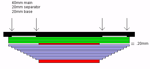
When the separator and base shim are the same diameter, the low speed stack acts independently of the high speed stack through the first part of the deflection range.
In Diagram 1 , it 's easy to see that the top shims can deflect without having any affect on the bottom stack.
In this case, if the separator shim thickness was .20mm, the top stack would deflect .20mm before hitting the bottom stack.
Diagram 1
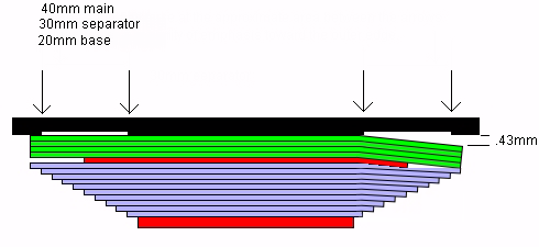
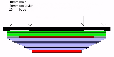
In Diagram 2, the main shim diameter is 40mm, the separator shim is 30mm and the base shim is 20mm. The separator diameter is half way between the main shim and base shim diameters.
Diagram 2
In this case, as the top stack deflects, the separator shim does not sit stationary, but actually bends downward, pushing the bottom stack away from the top stack. Because the outer edge of the low speed stack is relatively flexible, it eventually "catches up" to the high speeds stack and makes contact. The point of contact in this case is the total distance the low speed stack moves away from the face of the piston before hitting the high speed stack.
In this case, if the separator shim thickness was .20mm, the top stack would deflect .43mm before hitting the bottom stack. This is the point where the high speed stack becomes fully engaged (outer edge of low speed shims are making contact with outer edge of high speed shims).
Before the two stacks becomes fully engaged, it's easy to see that the high speed contributes to the stiffness of the low speed (before the outer edges make contact).
The flexibility of the low speed stack also determines the point of contact. If the top stack were made up of 6 - 40.10 shims (relatively flexible in comparison to the bottom stack), the point of contact would be less. If the top stack were made up of 6 - 40.30 shims (relatively stiff and inflexible) the point of contact would be more.
You could make the top stack so stiff and rigid that the low speed and high speed stacks would never touch. For example if you had 20 - 40.30 shims, the top stack would never flex enough to touch the bottom stack.
As a side note, the stock RM valve stack shown on Valving 103 goes from a 44mm main shim diameter to a 40mm high speed stack diameter, with two 34.15 separator shims. This stack is in essence a single stage stack, as the top stack does not make contact with the bottom stack (except possibly at the most extreme deflections).
When is a separator not a separator
Is there a point where the separator shim does not act as a separator, and just becomes another shim in the stack?
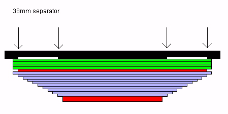
Below is a series of diagrams that shows the various possibilities of a separator diameter, starting with a 40mm main shim, a 38mm separator shim, and stepping down.
Diagram 3
Just looking at the diagram, we can see the 38mm shim (red) is just another shim in the stack and does not act as a separator.
Diagram 4
The 36 doesn't look much different.
Diagram 5
The 34 doesn't look much like a separator shim either. If the top stack was flexible enough, it might make contact with the bottom stack.
Diagram 6
The 32 may work as a separator shim, if the low speed shims were flexible enough.
If the 32mm shim were used as a separator, the bottom (high speed) stack would have major influences on the low speed stacks loads.
For example, if you added two shims to the bottom (high speed) stack, the increased stiffness of the bottom stack would in turn make the top (low speed) stack stiffer. In this case, increasing the high speed loads would also increase the low speed loads.
Diagram 7
A 30mm diameter shim is commonly used as a separator for the KYB 46mm pistons.
The point of contact for this stack, as calculated by the Shim Program is:
sep = .008" (.20mm) poc = .017" (.43mm)
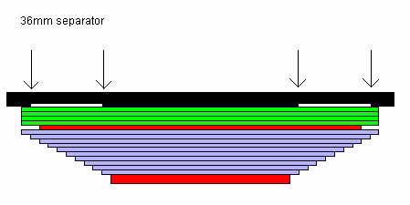
Diagram 8
sep = .008" (.20mm) poc = .014" (.36mm)
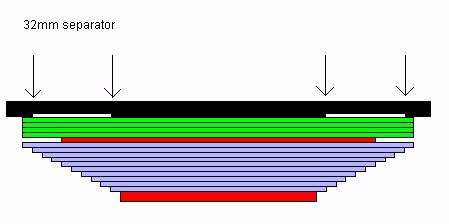
Diagram 9
sep = .008" (.20mm) poc = .012" (.30mm)
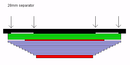
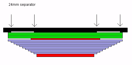
Diagram 10
sep = .008" (.20mm) poc = .010" (.25mm)
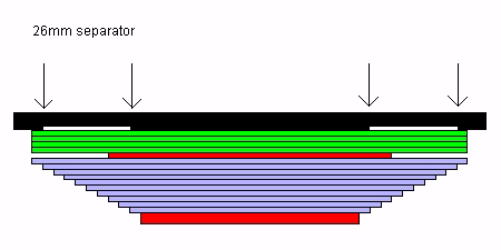
Diagram 11
sep = .008" (.20mm) poc = .009" (.23mm)
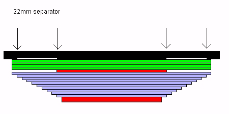
Diagram 12
sep = .008" (.20mm) poc = .008" (.20mm)
Now the separator diameter is the same as the base. In this instance, the poc is equal to the thickness of the separator.
Table 13 contains the stock compression valve stack for a 2004 RMZ 250. Using the dyno, we will compare the stock valving with 32 - 30 - 28 - 26 mm separators.
comp
(32 sep)
comp
(30 sep)
comp
(28 sep)
comp
(26 sep)
04rmz450
11 - 40.20
11 - 40.20
11 - 40.20
11 - 40.20
stk39s v4-v7
34.12 s
34.12 s
34.12 s
34.12 s
32.12 s
30.12 s
28.12 s
26.12 s
40.25
40.25
40.25
40.25
38.20
38.20
38.20
38.20
36.20
36.20
36.20
36.20
34.20
34.20
34.20
34.20
32.20
32.20
32.20
32.20
27.20
27.20
27.20
27.20
23.30 b
23.30 b
23.30 b
23.30 b
ips
dyno force (lbs/in)
dyno force (lbs/in)
dyno force (lbs/in)
dyno force (lbs/in)
5
161
159
156
153
10
258
254
247
237
20
431
422
410
390
30
582
569
554
528
40
718
701
684
656
50
846
827
808
780
60
974
952
932
906
70
1108
1084
1060
1038
Table 13
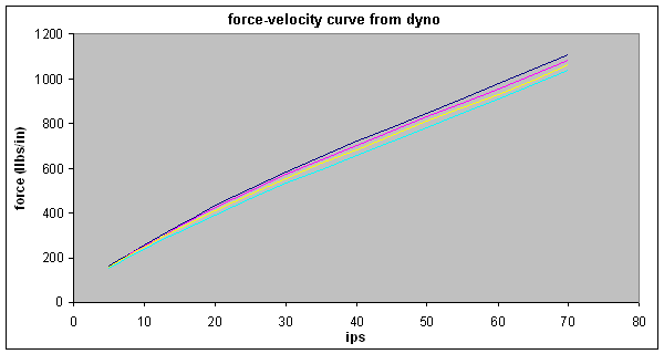
Chart 14 shows the load-deflection curves for the four stacks.
Chart 14
Stepping down in separator diameter affects both low speed and high speed damping.